www.linearcorp.com 17 eMerge Essential Installation Manual
Door Lock Operation
1. Present a valid card/PIN to a reader/keypad.
2. e controller will activate the door relay output associated with the particular reader (e.g.,
reader 1 will activate door lock relay 1).
3. e relay output is energized for a default time of 3 seconds.
4. As the user enters through the door, the door status input will change from closed to open.
6.0 Readers
Wiring the Readers
e control panel can accept up to 8 readers or keypads. Each reader port on the panel supports a
12VDC reader with Wiegand output format. Readers can be installed as primary (entry) readers
for each of the 4 doors as well as optional secondary (exit) readers.
e maximum power available for each reader is 750 mA @ 12 VDC. Determine the reader’s
power consumption by referring to the documentation included with the reader.
Wiring Readers
1. Remove power from the control panel.
2. Pull the reader wiring through a knock-out in the panel’s enclosure.
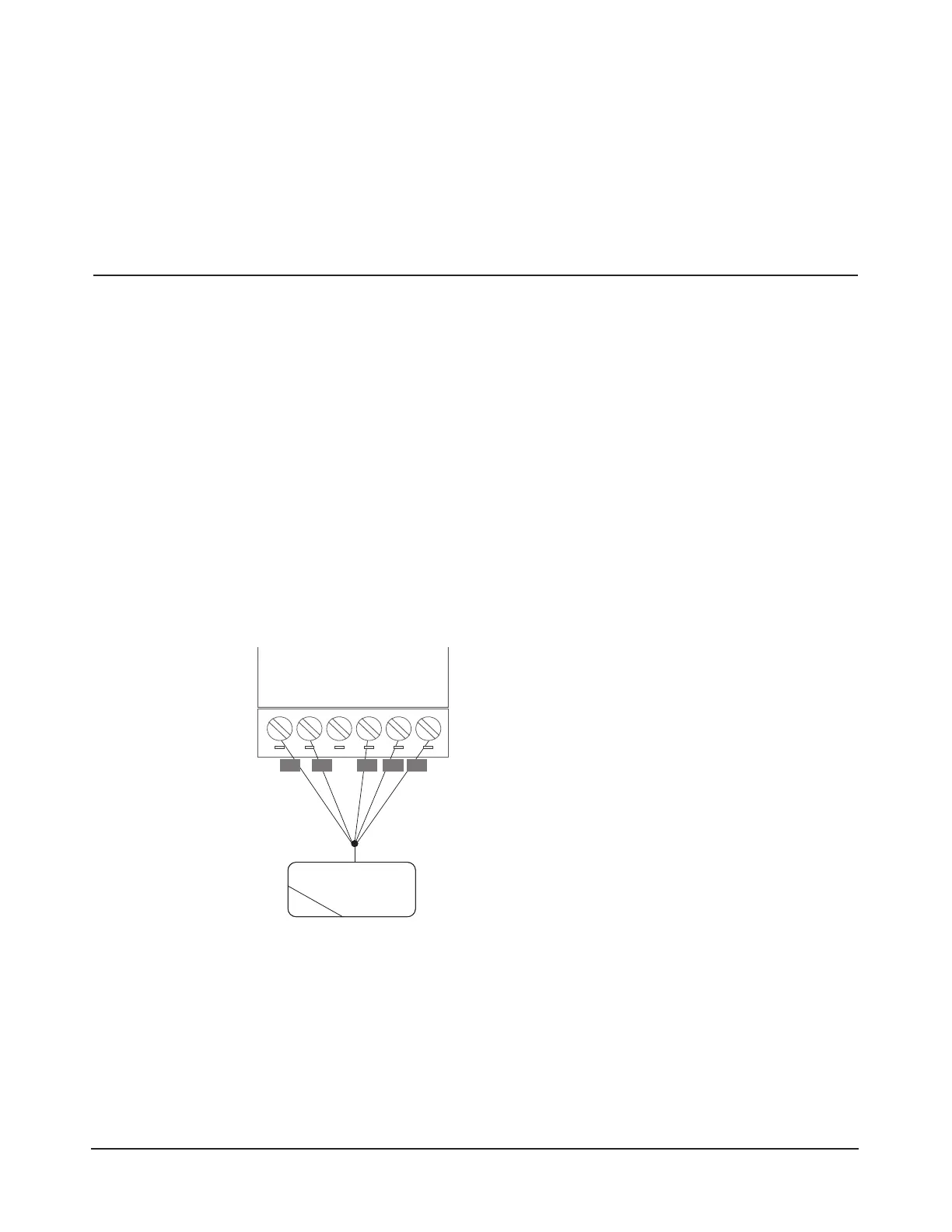
3. Connect the color-coded wires from the reader’s wiring harness to the appropriate location of
terminal strip as shown in Figure 6.1.
4. Remove excess shield to ensure that it is not exposed. An exposed shield can cause interference.
Tape o any exposed shield with electrical tape.
READER
+12V
LED
D0
D1
GND
DOOR 1
LOCK
SECONDARY READER 1
INPUT
GND
INPUT
GND
+12V
LED
Buzzer
D0
D1
GND
NC
C
NO
DOOR 1
RED BRN GRN WHT BLK
Figure 6.1. Reader Wiring
Caution: Improper power
wiring will damage the
fuse and void the war-
ranty.
Cable Specications:
Twisted, shielded 22
AWG (250 ft.) or 18 AWG
(500 ft.) Belden #9535 (5
conductor) or equivalent.
Please follow manufactur
-
ers installation require-
ments.