www.linearcorp.com 14 eMerge Essential Installation Manual
Wiring the Inputs
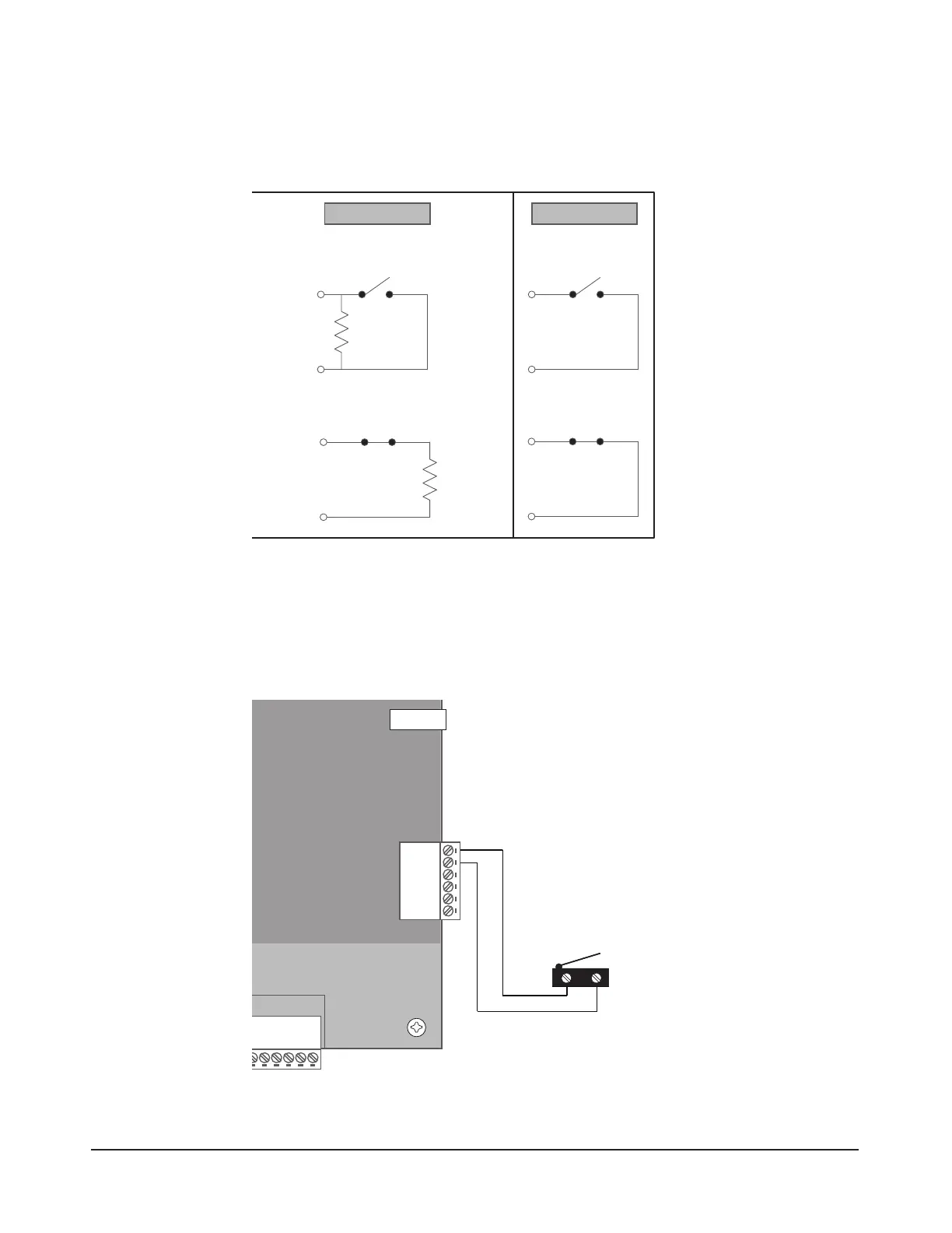
All inputs may be congured for normally open or normally closed contacts with supervision or
non-supervision. Use standard 1k ohm resistors for supervision. Refer to Figure 5.1 for the ac-
ceptable wiring congurations.
Normally Open
Normally Closed
Normally Open
Normally Closed
SUPERVISED UNSUPERVISED
Resistor Value = 1k Ohm
Figure 5.1. Input Circuit Congurations
Tamper Protection (Emerge Essential)
A tamper switch is mounted inside the enclosure for connection to pin 5 and pin 6 on the terminal strip.
If the eMerge Essential cover is removed for any reason the tamper switch will activate, triggering a con-
dition that can be linked to an event action in programming (e.g., send an e-mail or generate an output).
PIN 6
PIN 5
PIN 4
PIN 3
PIN 2
PIN 1
EMERGE ESSENTIAL CONTROL PANEL
6-pin terminal block
AUX RELAY 4
AUX RELAY 3
AUX RELAY 2
AUX RELAY 1
AUX INPUT 4
AUX INPUT 3
AUX INPUT 2
AUX INPUT 1
INPUT
GND
INPUT
GND
+12V
LED
Buzzer
D0
D1
GND
NC
C
NO
+12V
LED
Buzzer
D0
D1
GND
INPUT
GND
INPUT
GND
+12V
LED
Buzzer
D0
D1
GND
NC
C
NO
AUX IN 2
GND
AUX IN 1
GND
AUX IN 4
GND
AUX IN 3
GND
NC
C
NO
NC
C
NO
AUX
RLY 4
AUX
RLY 3
NC
C
NO
NC
C
NO
+12V
LED
Buzzer
D0
D1
GND
+12V
LED
Buzzer
D0
D1
GND
INPUT
GND
INPUT
GND
NC
C
NO
+12V
LED
Buzzer
D0
D1
GND
+12V
LED
Buzzer
D0
D1
GND
INPUT
GND
INPUT
GND
NC
C
NO
DOOR 1DOOR 2
DOOR 3DOOR 4
AUX
RLY 2
AUX
RLY 1
Enclosure Knockouts
Screw for cover
Enclosure Knockouts
Top Mounting Hole Top Mounting Hole
Factory
Installed
Tamper
TMP -
TMP +
FLT -
FLT +
GND
12VDC
Figure 5.2. eMerge Essential Tamper Input Wiring
Cable Specications:
22 AWG Belden or
equivalent. Maximum
distance: 2000 feet.