EasyManua.ls Logo

Link L1500 Series - User Manual

Link L1500 Series
31 pages
Print Icon
To Next Page IconTo Next Page
Loading...
Link L1500 Series Systems Manual
1 Products Covered. 2
2 System Description 3
3 L1500 Series Encoder/Transmitter 4
3.1 Operation 4
3.2 L1500 Connector Interface 10
3.3 L1500 HD Transmitter Description and Specification 11
3.4 Input / Output Connections 12
3.5 Mechanical 14
4 L1520 Camera Controller / Data Receiver – Optional 14
5 L2132/4 SD/HD Receiver 15
5.1 Controls 15
5.2 Operator Menus 15
5.3 Receiver Setup 19
5.4 Connectors 20
5.5 L2132/4 HD/SD Demodulator/Decoder Description and Specification 21
5.6 Input / Output Connections 21
6 L3070/50 DownConverter (Base) 23
6.1 DownConverter Description and Specification 24
6.2 Mechanical 24
7 L1255 Wireless Camera Control Unit (CCU) Interface 25
7.1 Controls and Setup 25
7.2 Connectors 25
7.3 Unit Description 26
8 Maintenance & Firmware Upgrades 28
8.1 L1500 RF / Up Converter and Camera Control Module Removal 28
8.2 L1500 Firmware Upgrades 28
8.3 Link ½ 19” Rack Based Products 29
8.4 L30*0 Down Converter Filter Change 29
9 Part Numbers for Link Research Accessories 31
Images are for illustration only and may differ from components supplied
Link Research Ltd www.linkres.co.uk Support UK/Europe + (44) 1923 474099 USA +(1)9786715700
Page 1 of 31 CL140045 Issue C Link L1500 Series System Manual
Question and Answer IconNeed help?

Do you have a question about the Link L1500 Series and is the answer not in the manual?

Summary

Products Covered

System Description

L1500 Series Encoder;Transmitter

3.1 Operation

Configuring the L1500 transmitter using the menu structure and push buttons.

3.1.2 L1500 Menus

Overview of BASIC, ADVANCED, and SERVICE menus for L1500 configuration.

3.1.3 Transmitter Setup

Settings for DVB-T, LMS-T, ASI, and Remux operations.

3.1.3.1 DVB-T Operation

Sequence of menu changes for DVB-T transmitter setup and bit rates.

3.1.3.2 LMS-T Operation

Sequence of menu changes for LMS-T transmitter setup and bit rates.

3.2 L1500 Connector Interface

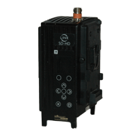
Details of the top, side, and lower panel connectors on the L1500 transmitter.

3.3 L1500 HD Transmitter Description and Specification

Description of the L1500 transmitter's main assemblies and its HD video formats.

3.4 Input; Output Connections

Details of SD input formats and specific input/output connector pin-outs.

L2132;4 SD;HD Receiver

5.1 Controls

Overview of the six membrane buttons and their functions on the receiver's front panel.

5.2 Operator Menus

Explanation of the receiver's top-level menu structure and available sub-menus.

5.3 Receiver Setup

Main configuration functions for the receiver, including down converter and demodulation.

5.4 Connectors

Details of connectors mounted on the rear panel of the L2132/4 receiver unit.

5.5 L2132;4 HD;SD Demodulator;Decoder Description and Specification

Description of the L2132/4 receiver's block diagram and its demodulator/decoder.

5.6 Input; Output Connections

Specifications for RF inputs, frame lock input, and other I/O connections.

Maintenance & Firmware Upgrades

8.1 L1500 RF; Up Converter and Camera Control Module Removal

Procedure for safely removing the RF/Up Converter and Camera Control modules.

8.2 L1500 Firmware Upgrades

Information on obtaining and performing firmware upgrades for the L1500 unit.

Link L1500 Series Specifications

General IconGeneral
BrandLink
ModelL1500 Series
CategoryCamera Accessories
LanguageEnglish