Rev: 05.23.2017 Page 10 Ground Control 3.0 Service Manual
Homing Jacks
NOTE: When components are added or replaced the system will need to be homed. Run the system by pressing
"FRONT" (Fig. 1G). A special jack error code should occur. If not, introduce the special jack error code.
NOTE: To introduce an error, disconnect 1 of the hall effect sensor wires from the controller. After
attempting to operate the disconnected jack, the touch pad screen will display an error. Reconnect
the hall effect sensor wire.
NOTE: In order to clear the special jack error code the jacks need to be "homed." In order to "home" jacks,
each jack must be able to retract a minimum of 6".
1. Extend all jacks to reach the 6" of minimum retract needed.
A. Press "FRONT" (Fig. 1G) to extend the front jacks (if required).
B. Press "REAR" (Fig. 1J) to extend the rear jacks (if required).
C. Press "LEFT" and "RIGHT" (Fig. 1H and Fig. 1I) simultaneously to extend the middle jacks (if
equipped and required).
2. Press and hold the retract button until all of the jacks begin to retract. The jacks will retract until they
reach the hard current limit.
3. The jacks are now “homed” and the special jack error code will be cleared.
NOTE: Note: If the jacks do not retract, an error should display on the touch pad screen. This is typically
caused by wiring interruption.
Component Replacement
NOTE: After replacing any of these
components, you will need to "home"
the jacks. See the corresponding
sections for instructions.
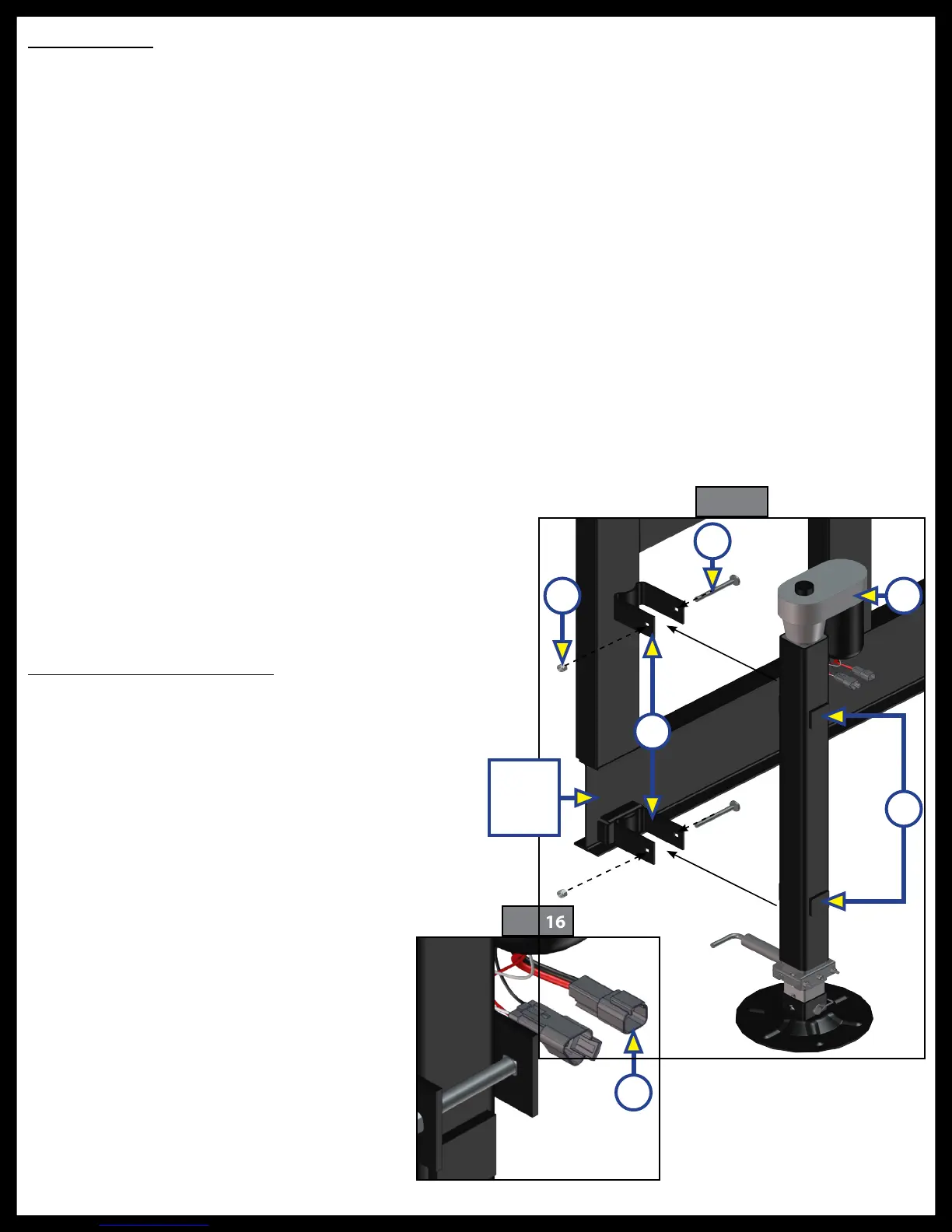
Landing Gear Replacement
1. Remove existing landing gear from the
trailer by removing the carriage bolts
and nuts holding the landing gear in
place in the brackets.
2. Using the new carriage bolts (Fig. 15A)
and nuts (Fig. 15B), mount the new
landing gear (Fig. 15C) in the mounting
brackets (Fig. 15D) so that the tabs
(Fig. 15E) on the new landing gear are
positioned between the mounting
brackets as shown in Fig. 15. Tighten
the nuts on the carriage bolts until
the bracket opening is less than 2
½
”
(Fig. 16).
3. Connect the wire harnesses (Fig. 16A)
to the landing gear motor wires and
run the harnesses to the compartment
where the controller will be mounted.
NOTE: LCI recommends zip-tying the
harnesses tight against the landing
gear motors to prevent damage to
the harnesses.
Fig. 16
A
Fig. 15
A
B C
D
E
Main
Frame
Rail

 Loading...