Rev: 07.03.18 Page 4
CCD-0001541
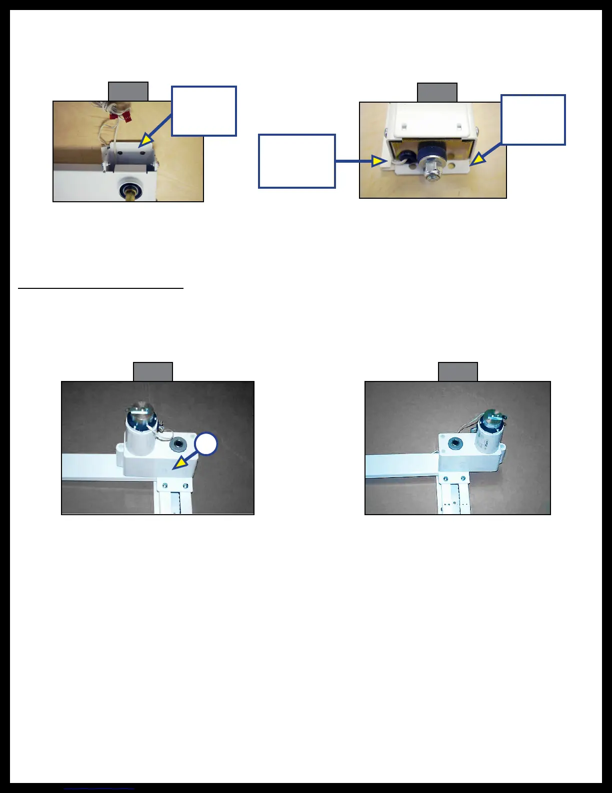
2. The
¼
" diameter wood or self-tapping sheet metal screws (OEM-supplied) must be used in all large
holes of the vertical rails, including the large double mounting holes at the top (Fig. 2) and bottom
(Fig. 3) of the rails, to prevent rail-twist.
Fig. 2
Upper
Mounting
Holes
Fig. 3
Lower
Mounting
Holes
Microswitch
Travel Limit
Wire
3. After the rails are installed:
A. Check the rails for squareness and parallelism.
B. Remove wooden packing strips.
Motor and Connecting Shaft
1. Motor may be installed inward (Fig. 4) or outward (Fig. 5) on the rear curb side rail. Motor orientation
is determined by the way the motor mounting plate (Fig. 4A) is attached. Attach the motor mounting
plate for the desired orientation using the four large countersunk bolts provided.
Fig. 4
Fig. 5
A
2. After attaching the motor mounting plate (Fig. 4A), attach the motor to the bed lift system by sliding
the hex connecting shaft into the motor. Install the two screws to hold the motor plate tight to the
lift rail.
3. Make sure that the drive (lower) trolleys (Fig. 7) are at the same height on both sides of the bed lift.
4. Install connecting shaft by sliding open end of shaft over the hex shaft on the side opposite the motor.
The motor side of the cross-connecting shaft needs to be completely seated against the c-channel over
the sprocket (Fig. 8).
NOTE: If a gap forms due to the timing shaft "walking", the surface area of the sprocket and timing shaft
are reduced and the sprocket will twist because of force of a smaller area.