Gocator Line Profile Sensors: User Manual
Gocator Web Interface • 256
Parameter Description
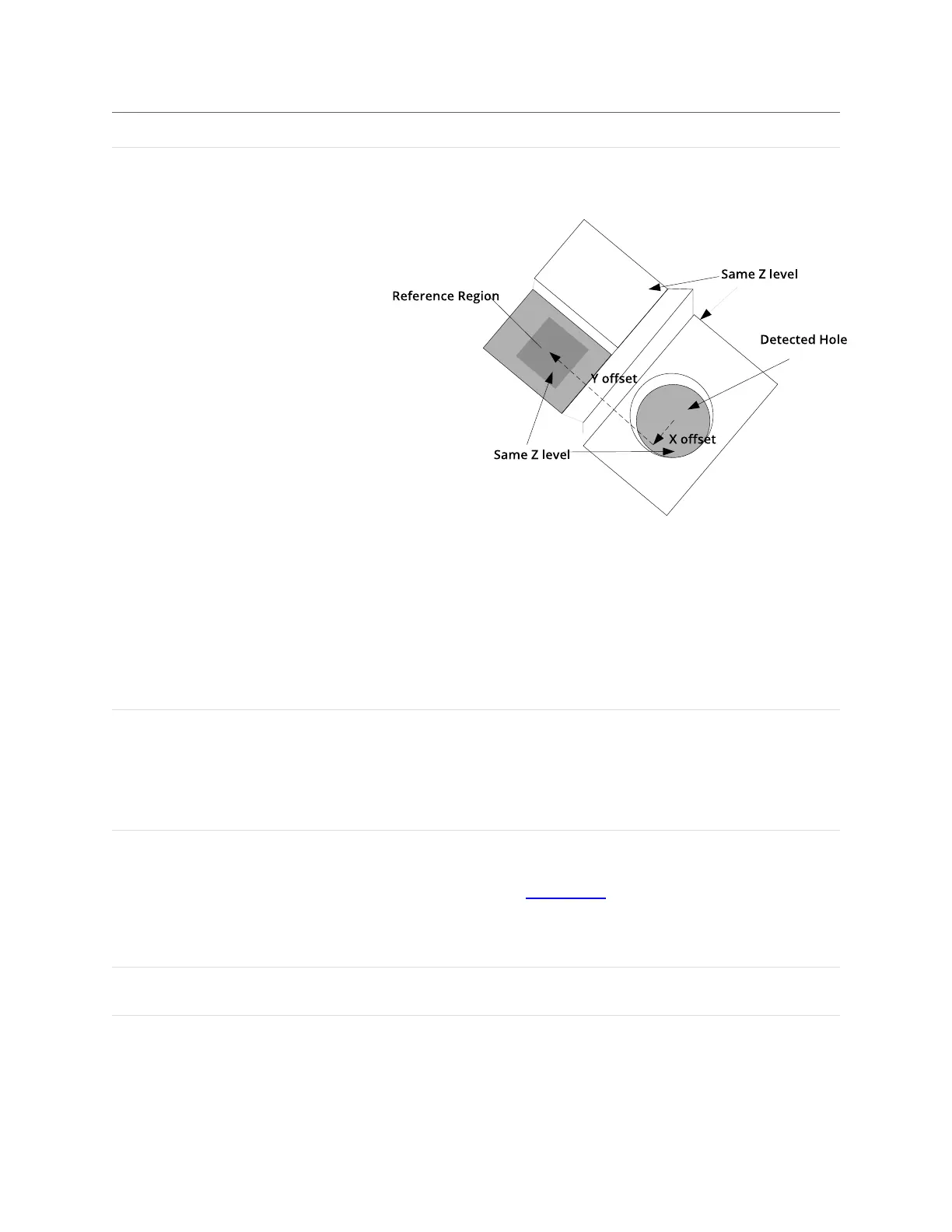
Reference Regions The tool uses the reference regions to calculate the Z position of the
hole. It is typically used in cases where the surface around the hole is
not flat.
When this option is set to Autoset, the algorithm automatically
determines the reference region. When the option is not set to
Autoset, you must manually specify one or two reference regions.
The location of the reference region is relative to the detected center
of the hole and positioned on the nominal surface plane.
When Reference Region is disabled, the tool measures the hole's Z
position using all the data in the measurement region, except for a
bounding rectangular region around the hole.
Tilt Correction Tilt of the target with respect to the alignment plane.
Autoset:The tool automatically detects the tilt. The measurement
region to cover more areas on the surface plane than other planes.
Custom: You must enter the X and Y angles manually in the XAngle
and YAngle parameters (see below).
X Angle
Y Angle
The X and Yangles you must specify when Tilt Correction is set to
Custom.
You can use the Surface Plane tool's XAngle and Y Angle
measurements to get the angle of the surrounding surface, and then
copy those measurement's values to the X Angle and Y Angle
parameters of this tool.
Filters The filters that are applied to measurement values before they are
output. For more information, see Filters on page 192.
Decision The Max and Min settings define the range that determines whether
the measurement tool sends a pass or fail decision to the output. For
more information, see Decisions on page 191.
 Loading...