EasyManuals Logo

Lockly Vision User Manual

Lockly Vision
31 pages
To Next Page IconTo Next Page
To Previous Page IconTo Previous Page
Page #11 background imageLoading...
Page #11 background image
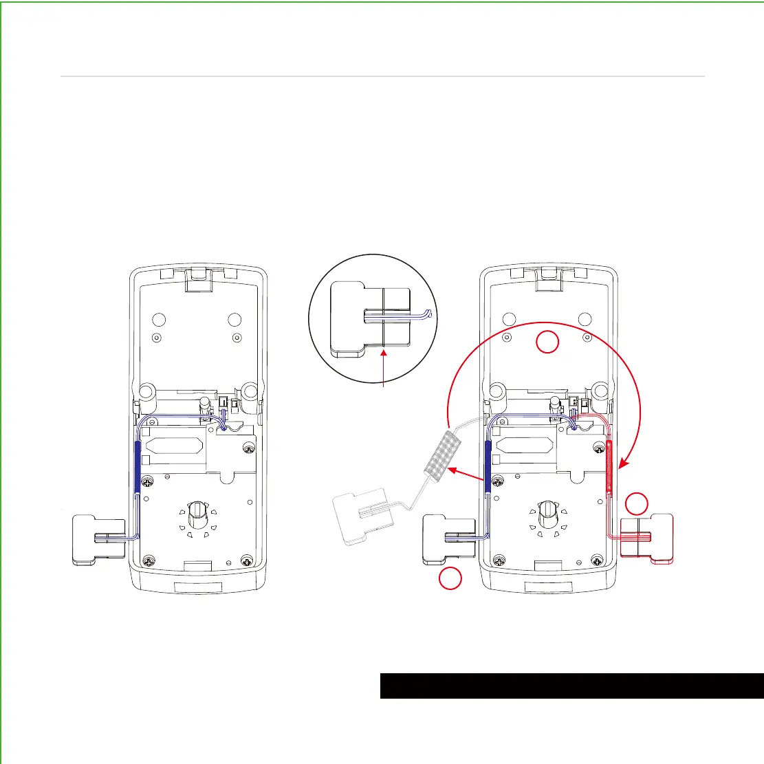
The interior assembly comes with the
pre-installed wired door sensor setup for a
right swing doors with 2 ¾" (70mm) backset*.
Trim excess part (P) for doors with 2 ⅜"
(60mm) backset as shown below.
For left swing doors, re-route the door
sensor wire through the side channel.
Pull the foam pad then re-insert to secure
the wire. Discard the excess part (e) for
doors with 2 ⅜" (60mm) backset as
shown below:
*Backset = distance of the door edge to the center of the cross-bore door hole.
DO NOT INSTALL THE SENSORS YET
Pull foam pad Insert form pad
PREPARING DOOR SENSORS FOR INSTALLATION
3
2
1
(P)
10
Step 4
continued
Trim excess here for
2 ⅜" (60mm) backset*

Questions and Answers:

Question and Answer IconNeed help?

Do you have a question about the Lockly Vision and is the answer not in the manual?

Lockly Vision Specifications

General IconGeneral
TypeSmart Lock
ConnectivityWi-Fi, Bluetooth
Fingerprint SensorYes
Voice Assistant CompatibilityAmazon Alexa, Google Assistant
MaterialZinc Alloy
User CodesUp to 99
KeypadYes
Night VisionYes
Two-Way AudioYes
Lock TypeDeadbolt
Power Source4 AA Batteries
Door Thickness1 3/8" to 2"
Security FeaturesPIN Genie
Camera Resolution1080p

Related product manuals