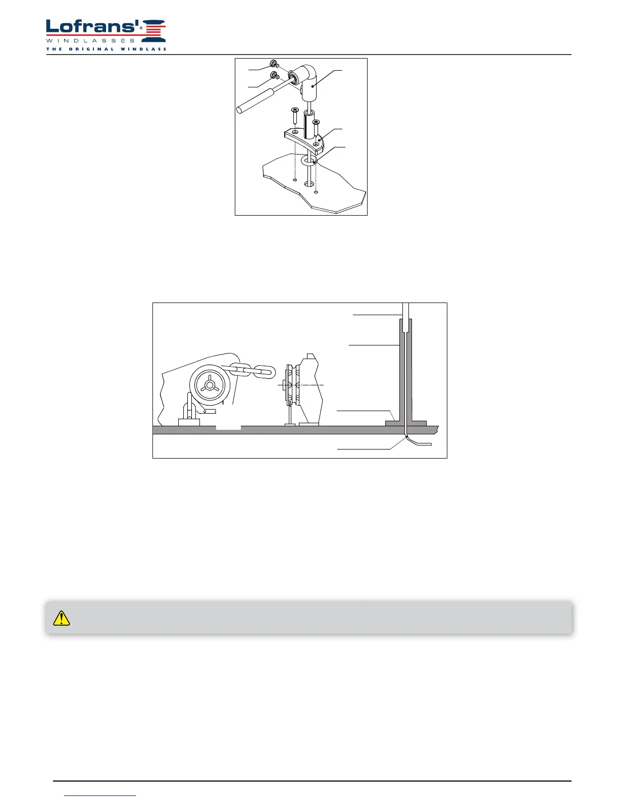
2.4 Installing the magnetic sensor for vertical shaft anchor windlasses
Drill a 4 mm (~3/16”) hole in the cover through which to thread the sensor cable.
Fasten Part A of the support with the two screws provided, after having positioned the O-ring in the lower part of the support.
Fit Part B with the magnetic sensor on support A and adjust its height until it is aligned with the magnet fastened on the gipsy.
Bring the sensor to a distance of about 3 mm (~1/8”) from the magnet and secure it in place by tightening screw G1.
Then tighten screw G2.
OR
A
B
G1
G2
2.5 Installing the magnetic sensor for horizontal shaft anchor windlasses
(see Fig. 2A – 2B – 2C)
Drill a 4 mm (~3/16”) hole in the cover through which to thread the sensor cable. Fasten Part A of the support with the two screws
provided, after having positioned the O-ring in the lower part of the support. Cut Part C to measure using a hacksaw. The sensor must be
positioned at a distance of about 3 mm (~1/8”) from the magnet. Fit Part C with the magnetic sensor on support A and x it in place using
an adhesive for plastic (two-component epoxy glue) or silicone. Using the same glue, attach the sensor to Part C.
Part.C
Part.A
magnetic sensor
sensore magnetico
Fi g. 2A
Fi g. 2B
Fig. 2C
sensor cable
cavo sensore
2.6 Installing the chain counter
(see connection diagram)
The chain counter must be positioned so that the display will be easy to read. It should not be exposed to direct sunlight.
The rear part of the instrument must be protected from contact with water or moisture. The instrument may be fastened to dashboards of
any thickness. The screws used for clamping must be of the selfthreaded kind and with a diameter of 3.5 mm (~9/64”) and a maximum
length of 10 mm plus the thickness of the dashboard. In the part to the rear of the dashboard there must be minimum clearance of 35 mm
(1” 3/8) and there must also be adequate access to perform installation and maintenance work. On the dashboard make a hole with a
diameter of 30 mm (~ 1” 3/16), as indicated, and 4 holes with diameters of 4 mm (~5/32”) for the chain counter clamping screws. Use
cutting nippers to cut the three pins on the back of the instrument, position the chain counter and fasten it to the dashboard by tightening
the four screws. If the dashboard already has a hole with a 54 mm (2”1/8) diameter, it is not necessary to cut the pins on the back. The
seal must be positioned between the chain counter and the dashboard.
ALWAYS DISCONNECT THE BATTERY PRIOR TO INSTALLATION