Controller Installation 4140 Controller Installation
EN ENTerminal 7 and 8 (Analog Input 1) and 9 and 10
(Analog Input 2)
Any suitable sensor for 24 V DC supply voltage,
current (signal) range of 4 – 20 mA and load
impedance of 100 Ω can be connected, e.g. LORENTZ
pressure sensor, LORENTZ liquid level sensor.
The sensor must then be congured in LORENTZ
Assistant.
If shielded cable is used (recommended), connect
the shield to the provided clamping terminals.
Terminals 11, 12, 13 (Relay)
This is a volt-free signal output that can be
congured in LORENTZ Assistant to control third
party devices. The relay oers NC ("Normally
Closed") and NO ("Normally Open").
If the relay is not activated NC and COM are
connected.
If the relay is activated NO and COM are connected.
l
WARNING – Do not connect any vol-
tage higher than 250 V AC or 30 V DC to
any of the terminals. The max. allowed
current running over the relay is 2 A.
Terminals 14, 15, 16 (Water Sensor)
Connect a water sensor to detect the presence of
water. This is usually installed on the suction side of
surface pumps for dry run protection. If no water
sensor is connected, a jumper wire must be installed
between terminals 15 and 16 (factory setting).
The sensor can be a resistive sensor type, which
pulls down the signal in case of water detection.
It is also possible to connect an active water sensor,
which needs a power supply. The supply can be
taken from terminal 14 (24V) and referenced to Pin
16 (GND). The maximum allowed current for the
sensor supply is 20 mA.
For the installation of a LORENTZ water detection
sensor (resistive type) remove the jumper cable
between terminals 15 and 16. Connect the sensor
to these terminal clamps (the polarity is irrelevant).
Other water detection sensors may require a
dierent connection.
Terminal 17 and 18
Connect the LORENTZ Sun Sensor module. This PV
module is used to measure the solar irradiation and
allows you to set irradiation dependent START / STOP
values for the pump. These settings can only be done
via LORENTZ LORENTZ Assistant.
l
WARNING – It is not recommended
to connect / change a sensor, while the
motor is running. Do not connect sources
with a voltage above 24 VDC.
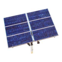
7.4.1.6 Solar Panel for Sun Sensor
l
WARNING – To avoid multiple starts
of the pump in twilight conditions,
the Sun Sensor must be installed and
congured according to COMPASS data.
Multiple starts due to an incorrectly
congured SunSensor can lead to
increased mechanical wear and damage
the pump. Such damage is excluded from
the warranty.
7.4.1. 5 Pump Accessory Wiring
a
CAUTION – Never let the pump run
dry. Dry running will damage the pump
and void the warranty. LORENTZ requires
a dry run protection for every pump
system.
Terminals 1 and 2 (Well Probe)
To protect the pump from being damaged by dry
running connect a suitable source low protection
switch to terminal 1 and 2. If dry run protection is
not needed, add a jumper wire between these two
terminals.
Terminals 3 and 4 (Remote Switch)
Connect any kind of external switch for remote
control of the controller. To run the pump the
switch must be closed (NC). If no switch is used the
terminals No. 3 and 4 have to be connected with a
jumper cable (factory setting).
Terminals 5 and 6 (Water Meter)
Install a water meter in the pipeline and connect it
to terminal 5 and 6. The output of the water meter
must be an impulse signal. The time between two
impulses must not exceed 5 minutes. The controller
can handle impulses with a frequency up to 1 Hz.
Select a water meter appropriate for the expected
ow. The ow can be viewed with the LORENTZ
Assistant software.
Motor lter
Due to the high voltages, high power and variable
frequency inverter technology used in solar pumping
systems, voltage spikes can occur which can have
an ageing eect on motor winding insulation. To
mitigate this eect, it is common to use a lter
between the PSk3 controller and the motor.
The level of accelerated ageing depends mainly
on the cable length and DC input voltage. Using a
lter reduces stress on the motor. The lter should
be connected directly on controller output motor
connections (U,V,W).
LORENTZ recommends using motor lters.
Further information concerning motor-lters can be
found in the knowledge base in PartnerNET.
a
NOTE – Cable sizing in LORENTZ
COMPASS sizing reports is based on
standard cables valid up to an ambient
temperature of 30°C. The installer must
check if the installation requires a
higher cable diameter due to ambient
conditions.
Electrical conduit
Electrical conduit is recommended. We recommend
the use of an electrical conduit (pipe) to protect
outdoor wiring from the weather, from human
activities and from damage caused by animals. If
you do not use a conduit, use a strong, high-quality
outdoor cable.
 Loading...