Pump System Sizing & Layout Diagrams 2120 Pump System Sizing & Layout Diagrams
EN EN
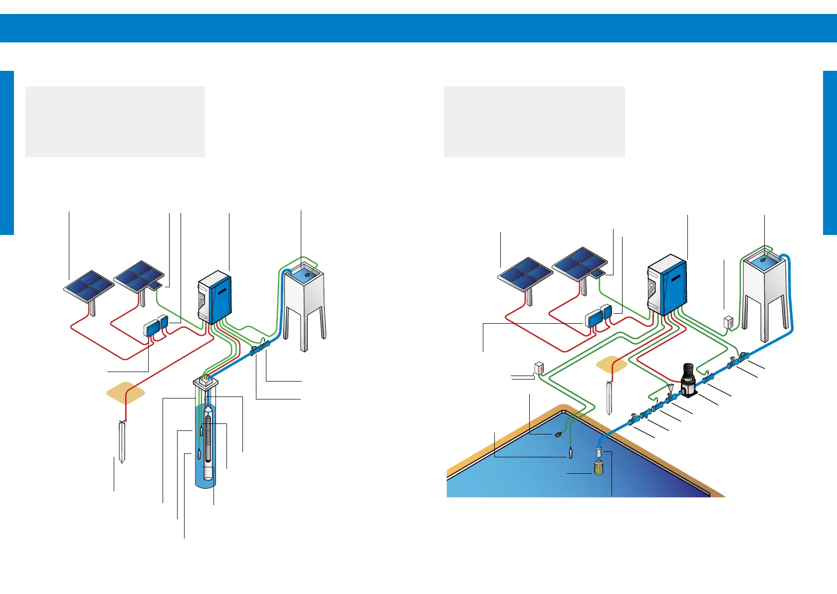
PV Generator
SunSensor
module
PV Protect
PV Disconnect
PSk3
Controller
Float
switch
water meter
valve
ller
pressure sensor
surface pump
water detection sensor
strainer
gate valve
surge
protector
grounding
rod
oat switch
liquid level
sensor
strainer
n o n - r e t u r n v a l v e
Surge
protector
6.3 System Layout: Surface Pumps
a
CAUTION – This graphic is an example
pump system layout diagram and for
ease of understanding only. For system
installation and wiring read and follow
the detailed instructions given in this
manual.
Figure 3: Surface pump layout
6.2 System Layout: Submersible Pumps
a
CAUTION – This graphic is an
example pump system layout diagram
and for ease of understanding only. For
system installation and wiring read and
the detailed instructions given in this
manual.
Figure 2: Submersible pump layout
PV Generator
SunSensor
module
PSk3
Controller
remote switch
(oat switch)
pressure sensor
water meter
PV Disconnect
PV Protect
grounding rod
splicing kit
well probe
liquid level sensor
safety rope
submersible pump
ow sleeve