Pump Accessories Installation 7372 Pump Accessories Installation
EN EN
9.2.1 Water detection sensor installation
This section is for the installation of the LORENTZ
water detection sensor only. This guide is not
universally applicable for sensors of other suppliers/
manufacturers.
LORENTZ recommends using a water detection
sensor to protect the pump against water shortage.
l
WARNING – Running the pump
completely dry will damage the pump
within seconds and void the warranty.
The purpose of the water detection
sensor is to sense the loss of water and
turn the pump o before it can run dry.
The sensor has to be installed close to the pump
inlet.
If the controller detects dry running it will stop the
pump. Following a run dry situation the pipeline
must be relled manually. Check the pipeline for
leakage.
The controller will delay the restart after the pipeline
has been relled for 15 minutes.
a
CAUTION – For submersible pumps
a jumper cable between the terminals 5
and 6 has to be installed.
CAUTION – If the water level of the
water source drops below the inlet of
the suction pipe the pump will suck in air
together with the water.
CAUTION – Air inside the suction pipe
can lead to cavitation and/or dry running
of the pump.
9.2 Water detection sensor
The water detection sensor protects the surface
pump from dry run. It is ONLY installed with surface
pumps.
For operation with submersible pumps the water
detection input terminals need to be bypassed with
a jumper cable. If the jumper is not in place the
controller will show “Source Low” and the pump will
not run.
The water water detection sensor needs to be
connected to the water detection input terminals.
For PSk3-7 to PSk3-15 please refer to „Figure 7:
Sensor terminal wiring example“ on page 30. The
wires of the LORENTZ water detection sensor need
to be connected to COM and Signal (polarity does
not matter).
Submersion depth – The maximum submersion
depth is 50 meters.
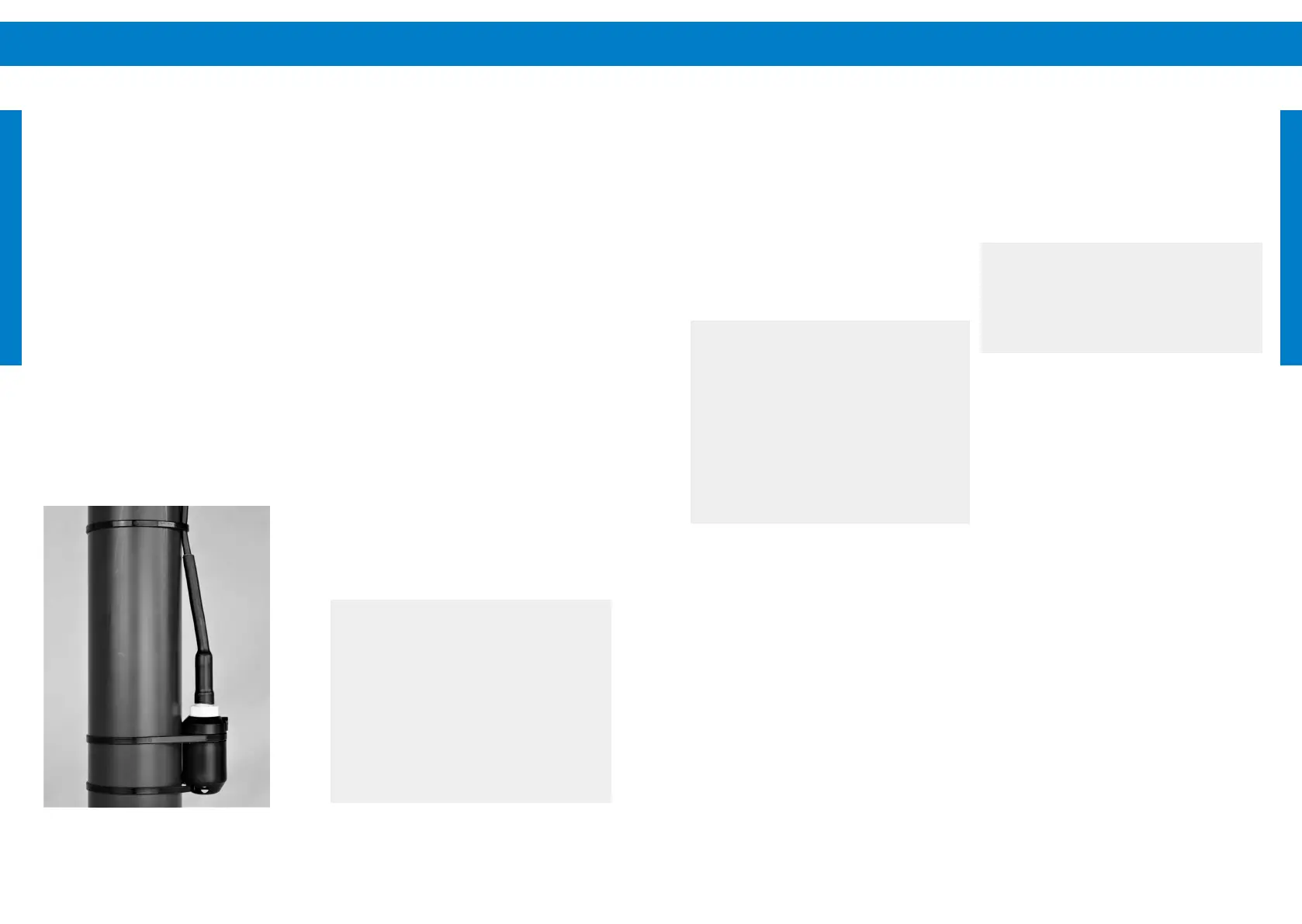
Fixing – Along with the probe two cable ties are
provided. For a pump that is to be installed in a
vertical position, clamp the probe to the pipe just
above the pump outlet, as shown in "Figure 38:
Well probe xing" below. Splice the two wires of
the probe using the splice kit components that are
packed with the probe. The assembly procedure is
the same as the main pump splice.
Wiring to the controller – Connect the Well probe to
the terminals as shown on the diagram. For PSk3-7
to PSk3-15 please refer to "Figure 7: Sensor terminal
wiring example" on page 30.
Figure 38: Well probe xing
Potential problems with the well probe in surface
water – The probe has a moving oat. It is highly
resistant to deposits and debris. However, the oat
can become stuck where algae or water creatures
are present in surface water.
Possible solutions are:
Fix the probe independently of the pump
and pipe (clamped to a weight, but not to the
drop pipe). This way, it can be pulled out for
inspection or cleaning without the need to lift
the pump. (This may not be feasible if the well
casing is smaller than 6 in)
Pull the probe out periodically (with the pump, if
necessary) for testing and inspection. The pump
should stop a few seconds after the probe leaves
the water.
Wrap the probe in a protective screen (berglass
window screen, for example).
Use a dierent type of oat switch. You can use
any switch that makes contact on rise (normally
open).Use an encapsulated switch instead of
the well probe if there is enough space for it to
operate properly, for example the LORENTZ oat
switch.
a
CAUTION – Never let the pump run
dry. Dry running will damage the pump
and void the warranty. LORENTZ requires
a dry run protection for every pump
system.
CAUTION – The well probe must be
positioned vertically, within 10°. If the
pump is not to be installed vertically, nd
an alternative way to mount or suspend
the probe, so that it is located higher than
the pump, and in a vertical position.