Installation overview 76 Installation overview
EN EN
2.1 Registration of components
Before you start the installation please register all components (e.g. Pump end, Motor, Pump Controller) on
Sites in partnerNET (Support, Sites) or by using the LORENTZ Assistant App. This is mandatory and needs to
be done to run the pump.
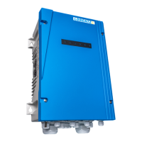
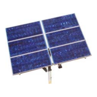
2.2 PV and Controller Installation
Please follow the manufacturers instructions for PV
installation. Every PV installation must be equipped
with a PV disconnect switch rated for DC. Suitable
switches are available from LORENTZ.
Please refer to "8 Pump Installation" on page 49
for more information on the requirements the PV
disconnect must meet.
Install the controller close to the PV array in a
shaded location to minimize cable length on the
input side.
For detailed information refer to "7.3 Mounting,
Space and Ventilation Requirements" on page 27.
2.3 Electrical installation
1. Pump wiring: The motor must be connected
to the terminals U, V, W, and PE. Observe rotation
direction.
For detailed information refer to "8.2.2 Wiring the
pump" on page 52.
2. Accessories wiring for PSk3-7 and PSk3-15:
Connect a well probe to terminals 1 and 2 (required),
remote control switches to terminals 3 and 4,
water meter to terminals 5 and 6, analog sensors
to terminals 7 and 8 or 9 and 10, water detection
sensor for surface pump to terminals 14, 15 and 16,
Sun Sensor module to terminals 17 and 18.
For detailed information refer to „7.4.1.5 Pump
Accessory Wiring“ on page 40.
3. DC input wiring: Connect the positive terminal
of the PV array to +, the negative terminal to −. The
max. input voltage provided by the PV array must
not exceed the specied max. input voltage of the
product.
4. AC input wiring: Connect the AC input phases to
the L1/L2/L3 and PE terminals.
For detailed information refer to „8 Pump
Installation“ on page 49 and "Table 2: Technical
Data of the PSk3 Controller" on page 12.
l
WARNING – Do not ground PV+ or
PV-. Grounding either PV+ or PV- while
using an AC power supply will result
in signicant damage and destroy the
controller.
5. Grounding: A protective earth connection must
be wired to PE .
For detailed information refer to "7.5 Grounding" on
page 46.
2.4 Pump Installation
Submersible pumps: Lower the pump into the water
source with caution, use a safety rope.
For detailed information refer to "8.2 Submersible
Pumps" on page 51.
Surface pumps: Install the surface pump on an
adequate foundation with sucient pipe sizing to
ensure ecient operation. Fill the pump with clean
water prior to starting it.
Depending on your pump system, refer to "8.3
Surface Pumps" on page 63 for detailed
information.