Pump Installation 5352 Pump Installation
EN EN
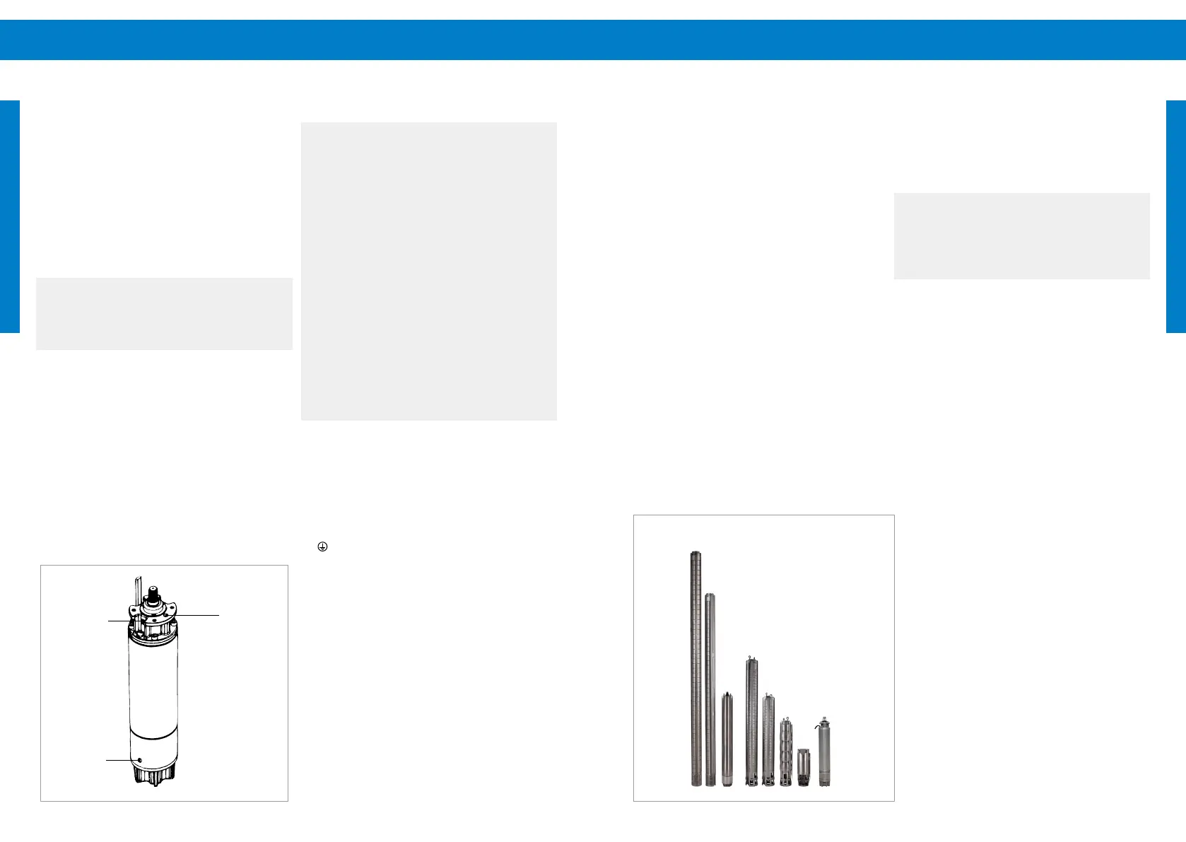
venting
hole
lling
hole
drainage
hole
Centrifugal Pumps:
Check of rotation direction after submersible pump
installation:
(5) Connect the pump to the controller and power
supply.
(6) Start the pump and check the delivered ow
rate.
(7) Stop the pump, disconnect the power supply and
change two of the three phase leads
(8) Start the pump again and check the delivered
ow.
(9) Stop the pump, disconnect the power supply
and compare the ow rates from point 2 and 4.
The wiring with the better ow rate has the right
rotational direction.
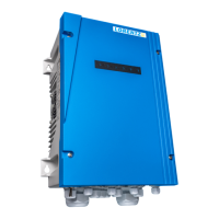
Figure 20: Example LORENTZ PSk3 submersible
pumps
8.2.3 Resistance measurement
We recommend checking the winding and
insulation resist ance before connecting the pump
to the controller. For a submersible pump these
measurements should be done BEFORE lowering the
pump into the well.
l
WARNING – Before starting any work
on the pump system, make sure that
the electricity supply has been switched
o and that it cannot be accidentally
switched on!
To measure the winding and insulation resistance
disconnect all motor leads from the controller. A
good quality multimeter is necessary to measure the
phase-to-phase resistance with an accuracy to the
rst decimal place. (“0.1 Ohms”). It is also advisable
to consider the resistance of the multimeter leads
when measuring very low values:
Hold the tips of the multimeter together and
note the value.
Always substract this value from your motor
resistance measurements!
The submersible motor is factory-lled with water,
but the motor lling must be checked before
installation.
The motor must be lled in vertical position (coupling
showing upwards, see gure below, "Figure 19:
Filling, venting and drainage hole").
To ll the motor with water, remove the lling and
venting screw. Fill clean drinking water into the
motor until the water ows out continuously out of
the venting hole, without any bubbles.
a
NOTE – Do not ll the motor using a
high pressure source such as a tap or
hose as this will cause unwanted bubble
formation.
To rell the motor open the lling, venting and
drainage screws to allow water to exit from the
drainage hole. Close the drainage screw and ll the
motor with clean drinking water as described above.
Figure 19: Filling, venting and drainage hole
8.2.2 Wiring the pump
a
CAUTION – No disconnect switches
must be installed between the motor
and the pump controller. Connecting the
motor wire to the switched-on controller
might irreparably damage it. Such
damage is excluded from the warranty.
CAUTION – If the pump wires are in
the wrong order, the motor will run in
reverse and the pump will not function
correctly. Damage may result. Check the
direction before installing the pump.
The proper direction is counterclockwise
when viewed from above.
CAUTION – Never let the pump run
dry. Dry running will damage the pump
and void the warranty. LORENTZ requires
dry run protection for every submersible
pump system.
The motor cables of the pump have a marking to
allow correct wiring. Connect the wires using this
sequence:
U: Motor cable phase 1
V: Motor cable phase 2
W: Motor cable phase 3
: GND
The submersible pump must be submerged in water
before checking the correct rotational direction. The
correct rotation direction for submersible pumps
is counterclockwise, viewed from the top. It is also
labelled with an arrow on the pump end.