Controller Installation 2726 Controller Installation
390
428
270
280
390
428
n 6.5
10
Ø15.4
A
A ( 1 : 1 )
50mm/2”
300mm/12”
300mm/12” 300mm/12”
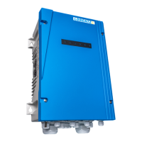
EN EN7.3 Mounting, Space and Ventilation
Requirements
The PSk3 controller must be mounted on a solid wall
or a rigid structure.
The installation plane must be concrete, metal, stone
or any other material with similar properties that
can absorb a tensile force of 200 N per screw after
the controller has been installed. The screw size
should be M5 or M6 and enable even fastening of
the controller. If the material does not allow proper
screw fastening, dowels can be used to support the
structure and enable it to absorb a tensile force of
200 N per screw. After installation no additional load
should be put on the controller, e.g. storing material
on top of the controller, which could increase the
load on the xation plane.
First, mark all drill holes. Refer to „Table 3: PSk3
controller dimensions for installation“ on page
26. Fit all screws, leave about 10 mm / 0.4” space
between the screw’s head and the wall. Hang the
controller on the wall. Finally, tighten all screws.
For grounding of the front cover the cover screws
must be tightened to a minimum torque of 2 Nm.
PSk3 controllers can be mounted side by side. Make
sure to keep the minimum spacing shown in „Figure
5: Minimum spacing for wall mounting“ on page
27.
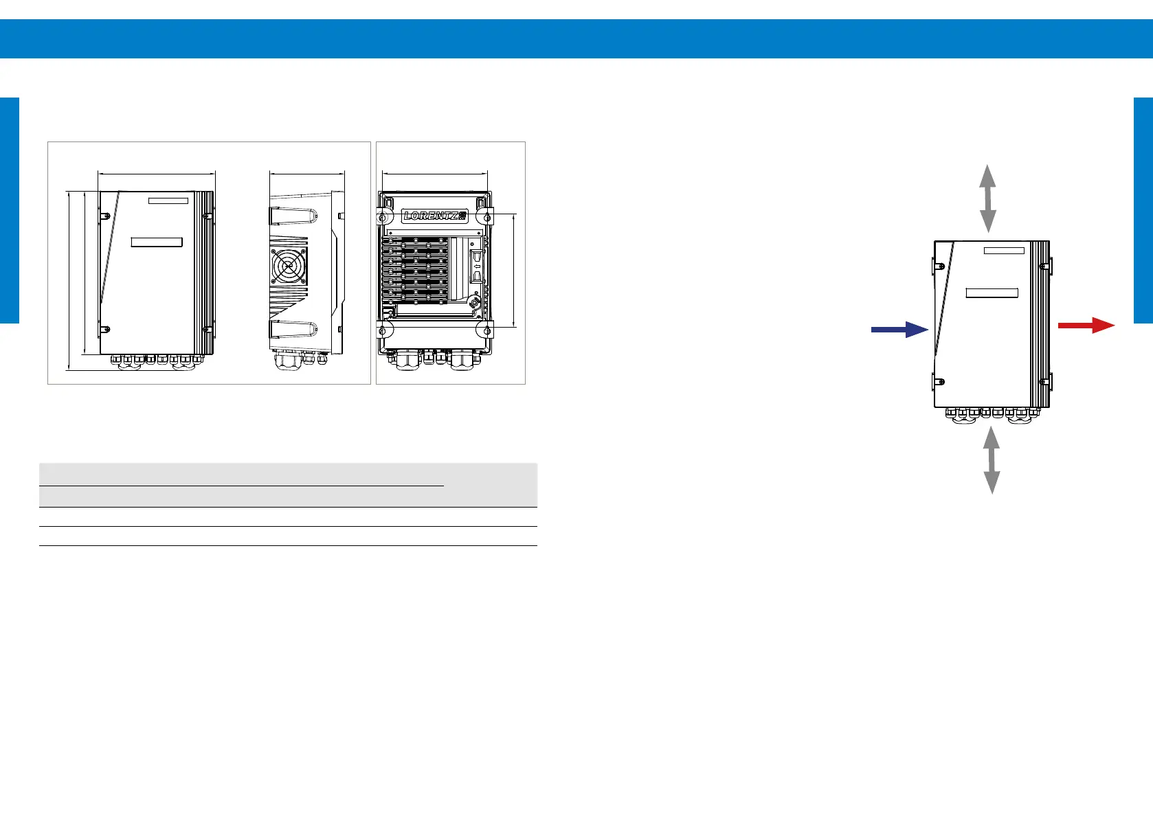
Figure 5: Minimum spacing for wall mountingFigure 4: PSk3 controller dimensions for installation
Table 3: PSk3 controller dimensions for installation
Dimension in mm [in]
Weight in kg [lbs]W1 W2 W3 H1 H2 H3 D1
280 250 280 390 270 428 180 15
[11.02] [9.84] [11.02] [15.35] [10.63] [16.85] [ 7.09] [33.07]