Pump Accessories Installation 7776 Pump Accessories Installation
10×D 5×D
D
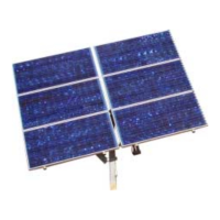
EN EN9.3 Water meter installation
For information on the water meter installation,
please refer to the manual of the manufacturer. Pay
attention to the installation position, ow direction
and the calming section.
Basic rule: The water meter should have 10 nominal
diameters straight pipe ahead of the meter and 5
nominal straight pipe diameters after to ensure
proper ow through the meter.
Figure 45: Water meter installation
Figure 46: LORENTZ water meter
9.4 Level sensor installation
The LORENTZ range of liquid level sensors use
pressure to measure the level of water in a well
or tank. The sensors can be used for long term
water level monitoring and also for pump control in
applications where a well probe cannot be used.
The Level sensor is connected to one of the two
Analog Inputs of the controller. Conguration of the
sensor is done with LORENTZ Assistant.
For further information about the level sensor please
refer to the COMPASS datasheet.
Figure 47: LORENTZ Liquid Level Sensor
9.5 Water Level Management Solution
(WLMS) installation
The LORENTZ Water Level Measurement Solution
(WLMS) accurately measures water levels in
boreholes and tanks. WLMS is a combination of
pressure sensor and plug-in barometer to provide
water level measurement for PS2 and PSk3 systems.
Used in conjunction with inbuilt software WLMS
allows you to record and monitor water levels in your
tank and control your system based on these levels.
For further information about the level sensor please
refer to the COMPASS datasheet and the WLMS
manual for installation and operation.
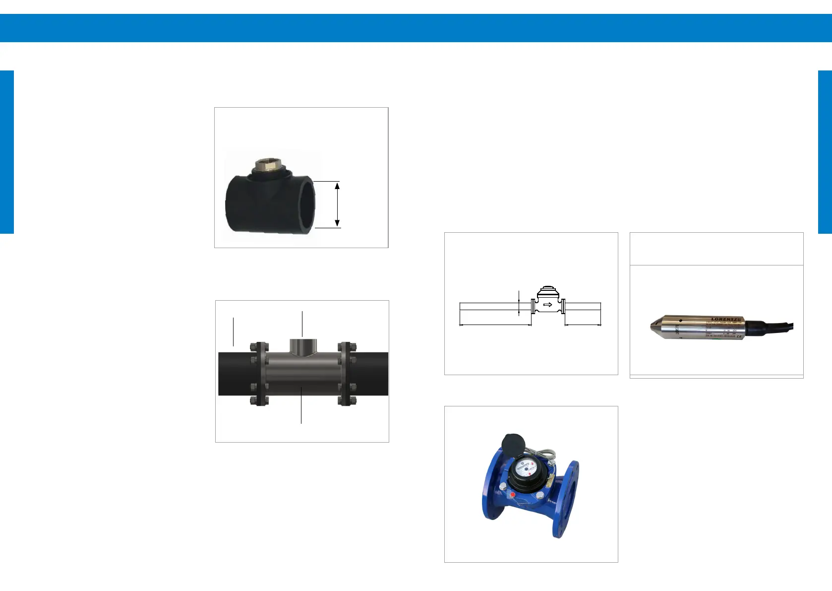
9.2.3 HDPE pipe
Option 1: Weld a tee-piece into the HDPE pipe, see
also „Figure 43: HDPE pipe tee-piece“ on page 76.
The tee-piece must have a 1” female thread (G1”,
whitworth pipe thread). The pipe diameter of the
tting should be the same as the pipe size. This piece
will be welded into the pipeline.
The tee-piece described above is not delivered by
LORENTZ.
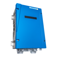
Option 2: Install an additional piece of steel or
stainless steel pipe with anges on both sides of the
HDPE inlet pipeline, see also „Figure 44: Steel ange
with adaptor in HDPE pipe“ on page 76 . Weld the
steel/stainless steel adapter for the water sensor on
the steel/stainless steel pipe according to chapter
"9.2.2 Steel/Stainless steel pipe" on page 74.
The steel / stainless steel pipe is not delivered by
LORENTZ.
After completion of option 1 or option 2, continue
with step no. 2. of chapter "Pipe system – We advise
that pipe expansion joints are used close to the
pump on both inlet and outlet to reduce noise and
vibration (see also „Figure 35: Pipe expansion joints“
on page 68). It is recommended that you install
a gate valve in the suction and discharge pipeline
close to the pump to avoid draining of the pipe while
cleaning (e.g. lters), repairing, servicing or replacing
the pump system.
Figure 43: HDPE pipe tee-piece
Figure 44: Steel ange with adaptor in HDPE pipe
1“ female thread (Whitworth pipe thread)
for the sensor housing
pipe diameter
D
HDPE pipe
adapter
steel / stainless steel
pipe