Pump Installation 6968 Pump Installation
EN EN
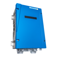
lter element
particle accumulation
l
WARNING – Inlet and outlet pipes
must be mounted to the pump housing
free of tension.
a
CAUTION – Make sure that the
suction pipe is sealed with no leaks,
otherwise the pump will not prime or will
prime insuciently.
CAUTION – The pumps are shipped
with plastic covers on the pump inlet and
outlet. Remove them before connecting
the pipes to the pump.
Check valve – A check valve at the inlet pipe is
needed to assure that the pump and its suction
pipeline remains completely water lled during
the time the pump is switched OFF. Always install a
check valve with one inch (1”) larger diameter than
the suction pipe in order to avoid too much suction
pressure drop. For example if the suction pipe size is
3”, then a 4” check valve should be installed.
8.3.4 Suction Head
The maximum suction head is limited by the local air
pressure, the water temperature of the medium, the
pipe losses and the NPSH (net positive suction head)
value of the pump.
a
CAUTION – If the suction pressure
in the pump is lower than the vapor
pressure of the uid, cavitation will
occur. Cavitation creates noise and
will damage the pump. Damage due to
cavitation is not subject to warranty.
To avoid cavitation, the pressure of the
uid must be maintained above its vapor
pressure at all points as it passes through
the pump.
The maximum suction head (H) must be calculated
in advance. Please refer to COMPASS and the
corresponding LORENTZ knowledge base article for
NPSH calculation.
8.3.5 Initial Start-up
a
CAUTION – Never start the pump if it
is not lled with water and has not been
vented. The pump and suction pipe must
be fully lled with clean water otherwise
the pump will be damaged.
8.3.5.1 Filling Pump with Water
The pump and the whole suction pipe must be fully
lled with clean water.
If the water level is higher than the pump inlet:
1. Close the gate valve in the outlet pipe and
loosen the air vent screw.
2. Open the gate valve in the suction pipe slowly.
3. Tighten the air vent screw when water streams
out continuously.
If the water level is below the pump inlet:
Suction pipeline and pump must be lled with water.
1. Close the gate valve in the outlet pipe and open
the gate valve in the suction pipeline.
2. Loosen the air vent screw and ll the water into
the pump through the ller pipe.
3. Fasten the air vent screw after the pump and
the suction pipeline are completely lled with
water.
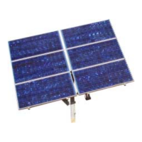
Pipe system – We advise that pipe expansion
joints are used close to the pump on both inlet
and outlet to reduce noise and vibration (see also
"Figure 35: Pipe expansion joints" on page 68). It
is recommended that you install a gate valve in the
suction and discharge pipeline close to the pump to
avoid draining of the pipe while cleaning (e.g. lters),
repairing, servicing or replacing the pump system.
Figure 34: Strainer 8.3.3 Installation and Handling
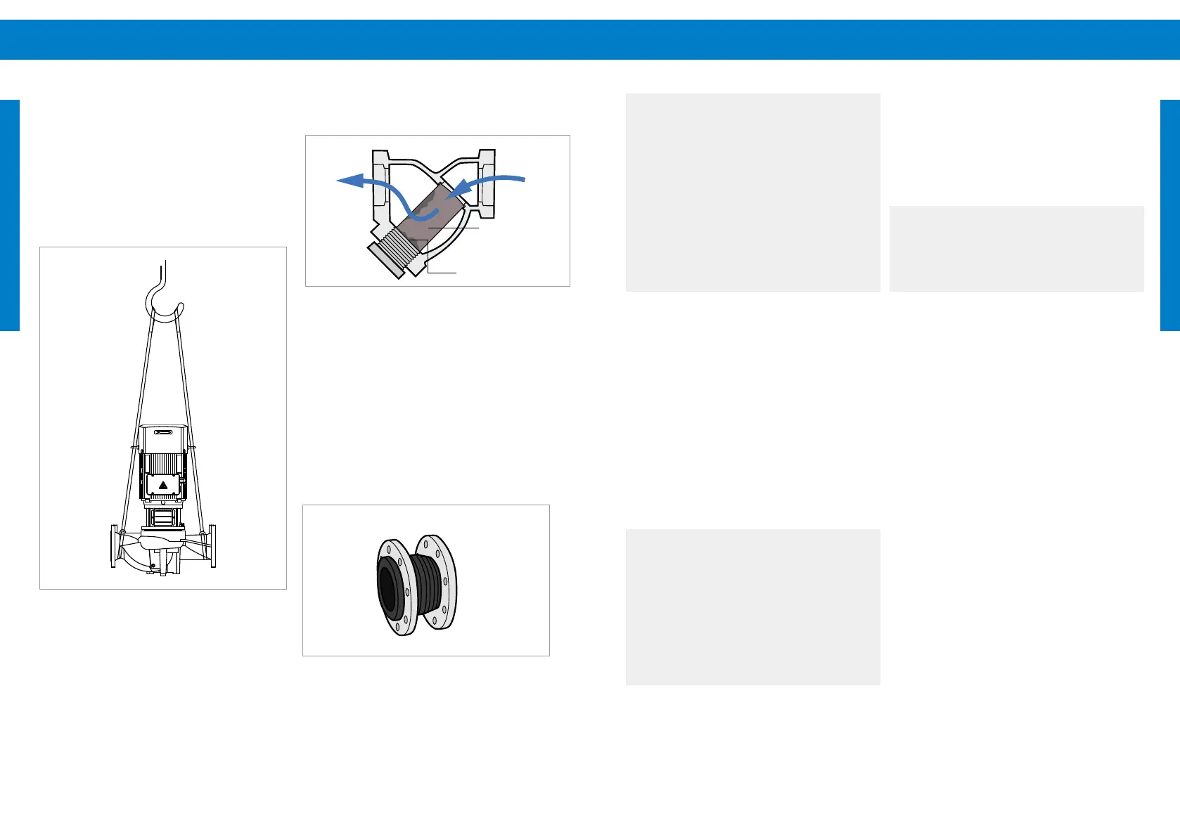
Handling – When lifting the CS-F pump use the
eyebolts at the motor housing. CS-G pumps must be
lifted by the base. Use the eyebolts to stabilize the
pump, see also "Figure 33: Pump handling/lifting"
below. It is recommended to use suitable lifting sling
belts.
Figure 33: Pump handling/lifting
Strainer – If pipelines are welded together metal
pieces might be present in the pipeline. Before pump
installation, the inlet pipeline must be carefully
cleaned. It is recommended to install a strainer
about 1 m / 3 ft in front of the pump inlet to avoid
pump damage due to any kind of impurities (see also
"Figure 34: Strainer" on page 68). The pressure
drop of the strainer must be considered in the
suction head calculation. Please refer to COMPASS
and the corresponding LORENTZ knowledge base
article.
Figure 35: Pipe expansion joints
unltered ow
ltered
ow