Controller Installation 2928 Controller Installation
EN EN
7.4.1 Controller wiring for solar only
7.4.1.1 Terminal description
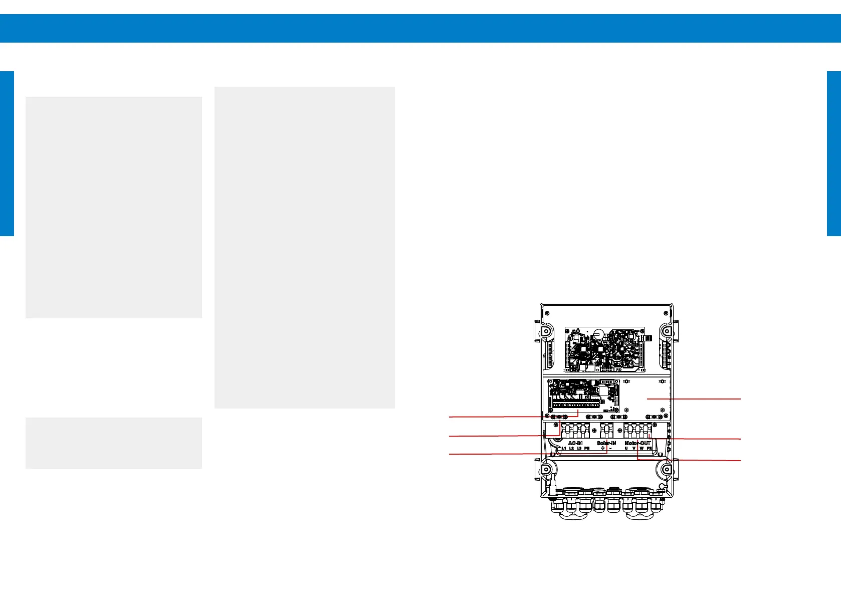
Open the housing by loosening the four screws
on the front cover. After removing the cover the
terminal can be accessed easily.
For “Solar-IN” and “Motor-OUT” open the clamp,
insert the wires and lock the clamps in place. Use
caution and keep hold of the clamp handles as the
terminals contain strong springs. Refer to „Figure 8:
Spring connector for "Solar-IN" and "Motor-OUT"“
on page 31. The length of wire stripping for these
terminals is 12-13 mm (0.5 in).
Figure 6: View of open PSk3 controller
For terminals 1 to 18 open the terminal by pushing
back the clamp handle with a screwdriver, insert
the wire, then release the handle to lock the wire in
place. Refer to "Figure 9: Spring connector for "Sensor
terminals 1-18 and fan terminal"" on page 31. The
length of wire stripping for these terminals is 5 - 6 mm
(0.2 in).
7.4 Wiring the controller
l
WARNING – All electrical
connections must be performed by
qualied experts only! Unqualied
handling might lead to shock, burns, or
death.
WARNING – Beware of high voltage.
Never work on a system connected
to power or within two minutes after
disconnection to avoid electric shock
hazard.
0
WARNING – Do not
dismantle the controller while
still connected to the power
supply! Before any installation,
maintenance or inspection
activities wait at least ve
minutes after the power supply
has been disconnected from the
controller!
Before starting to work on the electrical system
make sure that all components are disconnected
from the power source. Do not work on any
components when power is connected or within
ve minutes after disconnection. The controller
needs time to discharge.
Switch the system on only when all work is
completed.
a
CAUTION – The controller should
only be connected to power after
correct wiring or the controller might
get damaged.
a
CAUTION – Do not install disconnect
switches in the power wires between the
motor and pump controller. Connecting
the motor wires to a switched-on
controller may cause irreparable
damage. Such damage is excluded from
the warranty.
CAUTION – Solar-direct systems only
– Do not connect any electrical load to
the PV generator other than the LORENTZ
pump controller. Connection of a battery
charger, active solar tracker controller,
electric fence charger, or other load
simultaneously with LORENTZ PSk3
systems may interfere with the controller
and prevent proper operation.
CAUTION – Measure the voltage
before connecting power to the
controller. Voltage (open circuit) must
not exceed the max. DC input.
a
NOTE – PSk3 can be supplied by
solar and / or an AC source. This can
lead to an interaction of both sources,
especially if the system is not properly
installed. Special care must be taken
when installing the PSk3 controller in
hybrid conguration. Carefully read the
following chapters.
Placeholder for
optional board
Motor U V W
Motor ground
Sensor Terminals 1-18
Sensor Shield
Connector
Solar Input