Maintenance Instruction
5.8 Hydraulic lifter adjustment
Place the control lever for agricultural implement lifting and lowering to the neutral position. This ends by
adjusting the distance between the stop on the adjusting link and stop pin fixed on the lifting shaft.
5.8.1
Adjustment of agricultutral
implement max. position
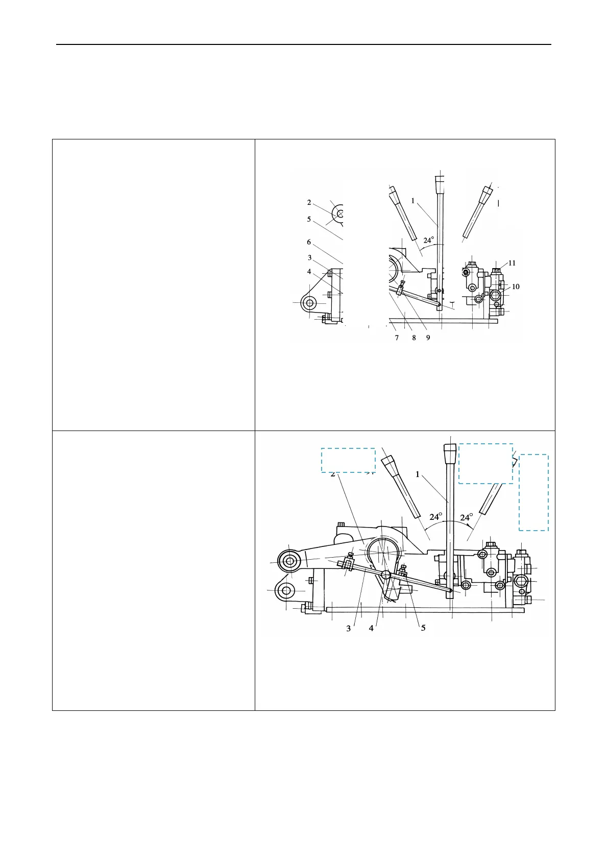
Firstly rotate the outer lifting arm2 to the
lifting direction to make the distance
between the lower end of inner lifting arm 3
and check pin 4 on the rear cover of lifter be
5mm (insert a 5mm block in air plug 5).
Make sure the distance between the inside
the check block 6 and check pin 7 be (9
~
10)
mm, then lock block 6 on thrust rod 8
with the bolt and lock the bolt with nut.
Fig.5-15 Adjustment for lifting position
1. Control handle 2.
Outer lifting arm; 3. Inner lifting arm; 4. Check pin; 5.
Air plug; 6. Check block; 7. Check pin; 8. Thrust rod; 9. Drop check block;
10. Hydraulic output plug; 11. .Adjusting valve
5.8.2
Adjustment of agricultutral
implement min. position
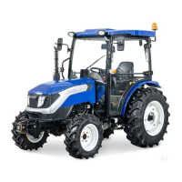
Firstly rotate the outer lifting arm 2 along
with lowering direction to min. position (at
this time, the piston i
n the cylinder is
pushed near bottom dead center). Then
make sure the distance between the stop 5
and stop pin 4 on the link3 should be (9~
10)mm.Then use the bolt on the stop4 to
lock it on the link.
Fig.5-16 Adjustment for descending position
1. Control handle 2. Outer lifting arm; 3. Thrust rod; 4. Check pin;
5. Drop check block;
eutrality
Hoisting
Neutrali
ty
Dr
op
pi
ng
65