Maintenance Instruction
5.2 Clutch adjustment
5.2.1 Clutch adjustment (single-acting)
To ensure the normal work of clutch, the clearance between
the release lever 4 working face of main clutch and end face
of release bearing 5 should be kept within
(2~2.5)mm. The
clearance between the end-
face of release lever 6 of
auxiliary clutch and release bearing 5 should be kept within
B=(10~11)mm. Continuous wear of clutch friction lining
will gradually reduce the clearance until it disappears.
Therefore check it regularly.
(1) Free travel of clutch pedal is adjusted as follows:
Firstly loosen the lock nut 3 on the release lever (see
fig.5-1). Then rotate the adjusting screw 2 to make sure the
distance between working face of three release levers 4 and
clutch pressure plate 1 shall be (45±0.125)mm, finally lock
with nut 3. Adjust the clutch front fork 4 (see figure 5-2) to
ensure the free travel of clutch pedal is(4-5.5)
mm, ensure
the clearance A between working face of release lever 4 and
end face of release bearing 5 is (2-
figure); after that, lock the nut 5.
(2) Work travel of clutch pedal is adjusted as follows:
Loosen the lock nut 1(see fig.5-2, unit: mm) and rotate the
limit screw 2 to keep the work travel of release rocker arm 3
within (30-35) mm. Finally secure the lock nut 1.
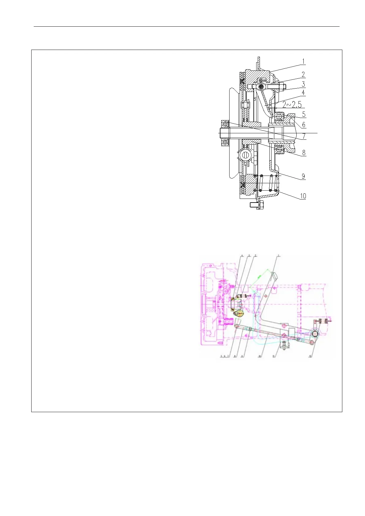
Fig.5-1 Single-action clutch
1. Pressure plate 2. Adjusting nut; 3. Lock nut 4. Release lever;
5. Release bearing 6. auxiliary bearing seat; 7. Bearing; 8.
Driven plate; 9. Clutch housing; 10. Clutch spring
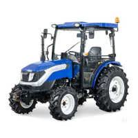
Fig.5-2 Clutch maneuvering system schematic
1. Pedal pressing; 2. Return spring of thrust bearing seat
3. Releasing bearing seat; 4. Release bearing; 5. Pin shaft; 6.
Split pin 7. Plain washer; 8. Front fork of lever; 9. Nut; 10.
Operation lever 11 Pedal check plate; 12. Return spring
54