L-STAT User Manual 39 LOYTEC
Version 1.0 LOYTEC electronics GmbH
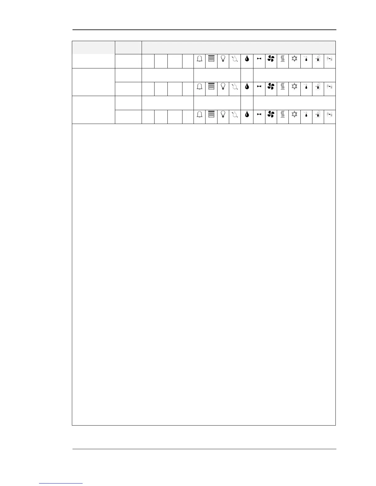
These registers hold the configuration of the 16 display values.
For both, unit_lstat and unit_modbus the following values are possible:
Bits 0-11 of the higher address of each configuration register indicate the symbols that are
displayed along with the corresponding display value.
These two bits define if the value displayed is taken from a display_value register at address
64 to 79 (see Table 11 on Page 25) or from a sensor_value register at address 48 to 56 (see
Table 10 on Page 24). The following states are valid:
0 – defines that the value is taken from a display_value register that has to be set via
modbus
1 – defines that the value is taken from a sensor_value (+ offset_value) register that is
automatically updated with the current sensor value
Visible for system administrator
These two bits define if the display value is visible for the end user and/or the system
administrator. If set to ‘1’ the value will be visible.
See Table 31 on Page 43 for example configurations of display values or set points.
* Please note that config_display_value_3 register is only configured as above per default
for LSTAT-802-Gx-Lx devices for displaying the actual CO
2
level. Otherwise all bits of
this register are set to ‘0’.
is used to provide information about the semantic meaning and the
source of the value. For further information please see Table 30 on
Page 42.
if set to ‘1’ the corresponding offset_value can be edited in
CALIBRATION-mode (only capable if DSEU or DSSA is set to
‘1’)
defines a unit with which the corresponding display value appears
on the LCD
defines a unit that the corresponding display value register appeare
on Modbus
display source for end user
diplay source for system administrator
Table 28: Display Value Configuration