L-STAT User Manual 30 LOYTEC
Version 1.0 LOYTEC electronics GmbH
3.4.2 Device Settings
The device settings contain data to configure the device and the user interface. This
registers are also accessible through the button interface in EDIT-mode for the system
administrator. The data is stored persistently and will be preserved during power loss.
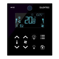
This register contains the configuration for the Modbus port of the LSTAT device.
Compare Table 5 on Page 17 for device settings editable via the user interface.
defines the parity bit used for Modbus communication. Valid are:
0x0 – odd (odd parity bit, 1 stop bit)
0x1 – even (even parity bit, 1 stop bit)
0x2 – none (no parity bit, 2 stop bits)
defines the Modbus baudrate, following values are valid:
0x0 – 1200
0x1 – 2400
0x2 – 4800
0x3 – 9600
0x4 – 19200
0x5 – 38400
0x6 – 57600
0x7 – 115200
defines the Modbus slave address.
Valid addresses are 1(0x01) to 247 (0xF7).
Table 18: Modbus Parameter
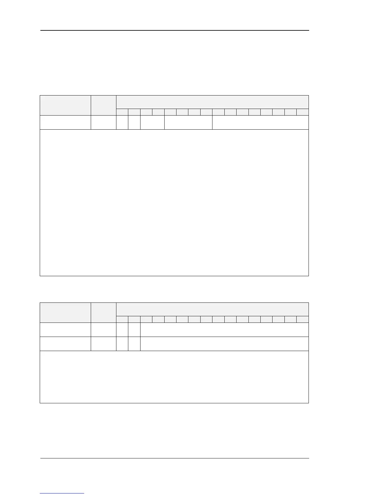
pincode_system_
administrator
pincode_system_administrator defines the pincode for the system administrator. If set to
0000 the pincode is disabled. Possible values are 0000 (0x0000) to 9999 (0x270F).
pincode_end_user defines the pincode for the end user. If set to 0000 the pincode is
disabled. Possible values are 0000 (0x0000) to 9999 (0x270F).
Compare Table 5 on Page 17 for device settings editable via the user interface.