7
;=A57!==IgYfAUbiU`
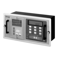
4-2 Special function switch
Enter the special function mode by pressing the ‘Func switch’. If you press the ‘Func
switch’ again
the standard mode comes. In the special function mode the followed measuring switches
display the
new data as described below.
1) V switch: Display the PT ratio setting value of the dip switch in the back plate.
2) A switch: Display the CT ratio setting value of the dip switch in the back plate
3) W switch: Display the address setting value of the telecommunication unit. If there is
no communication just display ‘- - ‘.
4) VAR switch: Display the number of operation time of the CB, which is connected to the
CB ON input contact. .
5) WH switch: Display the let through time [hour unit] of the CB, which is connected to
the CB ON input contact. When the time is over 9999 hours, it display the time by the
bargraph on the 10000 hours unit.
6) VARH switch: Display all the measured data by the following sequence at few seconds
intervals.
(V→A→W→VAR→WH→VARH→F→PF)
7) F switch: Display the wire connection type of the measured equipment.
8) PF switch: Display the average power factor, which was calculated by use of value of
the WH & VARH
4-3 Etc.
1) Clear switch
. The clear switch in the backplate reset the WH & VARH value to “0”
. The users should press the reset button when you first install the system.
2) CPU Reset button
. The CPU reset switch in the backplate clear all the data in the CPU. When you found
the operations
of the equipment is unusual, you can press and restart.
3) Fault Reset Switch
The alarm relays open when press ‘Reset switch’, located in front of equipment.
The fault LED turns off, when remove the causes of the fault.
 Loading...