Do you have a question about the LS Industrial Systems GIPAM and is the answer not in the manual?
GIPAM detects CPU operation errors and indicates caution and reason.
Records 255 faults and events, aids in system error analysis.
Lists measured parameters like voltage, current, power, power factor, frequency, zero phase voltage.
Lists protection relays like OCR, OCGR, UVR, OVR, OVGR, SGR.
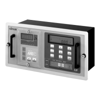
Details of front panel components and their functions with key numbers.
Block diagram showing the internal architecture and connectivity of the GIPAM device.
Details input specifications for wiring type, frequency, voltage, current and measurement results.
Explains calibration modes and measurement display functions.
Covers DIP switch settings and calibration of input energy amount.
Explains display of operating status and functions of various keys.
Details how to set protection functions and explains time delay curves.
Describes how fault status is indicated by LEDs and the LCD display.
Provides formulas for Standard Inverse, Very Inverse, Extreme Inverse, and Long Inverse time delay curves.
Steps for installing the device including setting ratios, address, power, and inputs.
Visual guide to DIP switch locations and functions for CT Ratio, Wiring, Calibration, and Mode.
Wiring diagram for a single-phase two-wire system connection.
Warning against connecting with noisy devices to prevent interference.
Details communication specs: speed, cable length, insulation, connection type, and cable specs.
Explains event recording and synchronization for devices.
Illustrates network topology connecting GMPC, GIMAC, GIPAM, U-RTU, and DPR units.
Provides common issues, causes, and solutions for device problems.
Lists GIMAC-II features: LCD display, keys, I/O terminals, and protection cover.
Explains how to display measurement data for voltage, current, power, watt hour, power factor, and frequency.
Steps for setting CT/PT ratio, mis-operation mode, wiring type, and communication address.
Wiring diagram for a 3-Phase 4-Wire system with 3 CTs and terminal blocks.
Identifies and describes the front panel components and indicators of the GMPC-III.
Introduces GMPC-III as an interface supporting I-Net, RS-232/485 and MODBUS protocols.
Illustrates network topology connecting GMPC, GIMAC, GIPAM, U-RTU, and DPR units.
Details GMPC's RS-232/RS-485 ports for interfacing with control systems.
Explains synchronization between GMPC and remote systems, and among GMPCs.
Covers connecting power and communication lines, including RS-232 connector details.
Details self-test, error display, and setting Hour/Minute/Second.
Defines the structure of data frames used for transmission between GMPC and Host systems.
Describes the detailed steps and data exchange for precision synchronization.
Details the command and response for reading the status of GMPC.
Describes the format and meaning of status data transmitted from GIMAC-II.
Describes commands for selecting control points and setting SOE events.
Describes requesting and receiving status data for GIPAM and SOE GIPAM.
Outlines commands for requesting various setting data like measuring part, OCR/OCGR, OVR/UVR, OVGR/SGR, and SOE.
Defines names for data types: Signed Register, Long Integer, Floating Point, and Bit in Register.
Details Modbus address settings for GIMAC-II for status and fault data queries.
Guides on setting the COM port for connecting with GMPC III MODBUS.
Explains how to define tags: Name, Type, Comments, Initial Value, and Access Name.
| Brand | LS Industrial Systems |
|---|---|
| Model | GIPAM |
| Category | Relays |
| Language | English |