Chapter 8 Modbus Communication
8-9
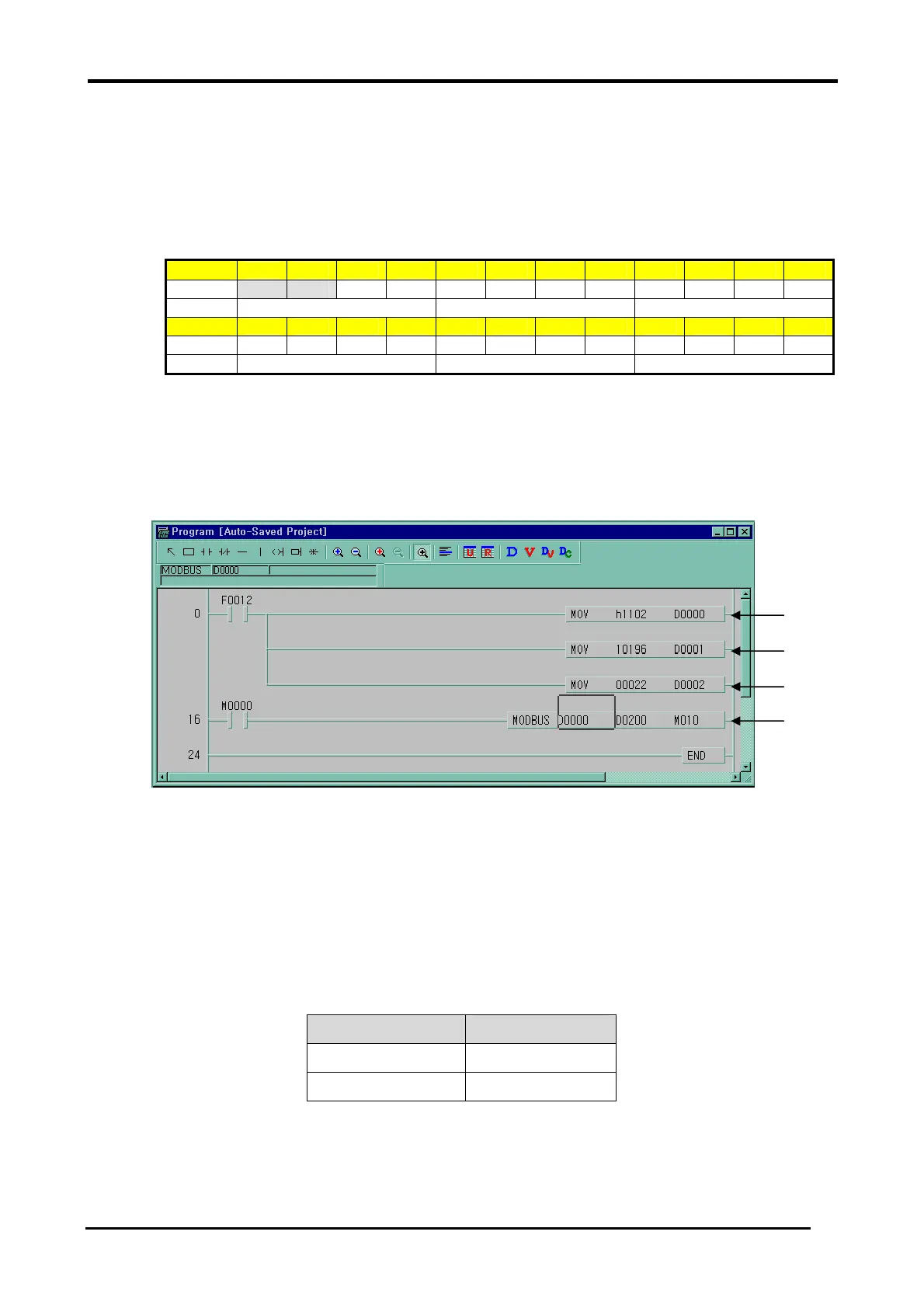
Example program 2
The master reads status of the input contact 10197 ~ 10218 of the slave station no. 17.
The input contact of the slave station is supposed to be as follows and the data that are read is
saved in Internal relay M015.
Input
10220 10219 10218 10217 10216 10215 10214 10213 10212 10211 10210 10209
Status X X 1 1 0 1 0 1 1 1 0 1
Hex 3 5 D
Input
10208
10207 10206 10205
10204
10203
10202
10201
10200 10199 10198
10197
Status 1 0 1 1 1 0 1 0 1 1 0 0
Hex B A C
• The status of input contact 10219, 10220 is redundancy
• Data is sent starting from the low bit by byte unit. If the deficient bit of a byte is filled with 0. An
example of sending the above data is as follows.
Example 2) AC DB 35
It designates slave station and function code (No. of station : h11(17) , function code : h02 )①
Address setting②
- Address ‘0’ at MODBUS protocol means address ‘1’ actually. So if you want to designate
address ‘10197’, write address ‘10196’
Reading number setting (Reading number is 22 from 10197 to 10220.)③
This is MODBUS Communication instruction.④
- The data transmission starts lower byte. The remnant part of byte is filled with ‘0’
⑤ Stored data at D200, D201 are:
Device Stored data
D200 h AC DB
D201 h 00 35
①
②
③
④
 Loading...