Chapter 7 Exclusive Functions for iS7 Inverter Control/Monitoring
7-18
▶ Application and exemplary program
1) Set up inverter parameters as follows. Especially, enter 0305Hex which is the address of the inverter
operation status (app. 4-1, page 4, Appendix) in the APO76 (PLC Rd Data1).
Code Function Name Set Value Remark
DRV01 Cmd Frequency 12.00 Hz -
DRV06 Cmd Source Keypad -
DRV07 Freq Ref Src Keypad-1 -
APO76 PLC Rd Data1 0305 Hex -
2) The APO76 (PLC Rd Data1) corresponds by 1:1 with the PLC option’s special register D4474.
Therefore, the value in the D4474 is the data (current operation status of the inverter) stored in 0305Hex
which is the address of the inverter operation status registered in the APO76 (PLC Rd Data1).
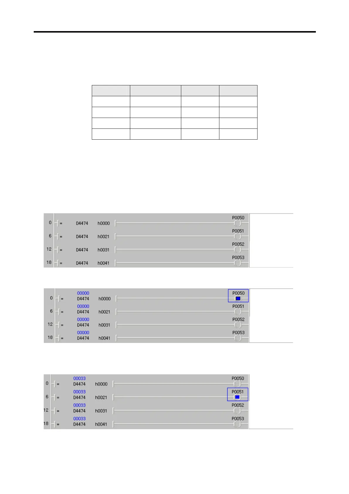
3) For an example with the ladder program below, PLC option can monitor the current operation status
(stop, accelerating, decelerating, constant speed, etc.) of the inverter.
4) In stopped status, the D4474 is “h0000” (see common area of inverter)
5) Now, press the FWD key on the digital loader of the inverter to provide it with forward operation
reference. During forward operation, the D4474 is h0021 (see common area of inverter)
Stop Status
Forward Accelerating
Forward Decelerating
Constant Speed for
Forward
Stop Status
Forward Accelerating
Forward Decelerating
Constant Speed for
Forward
Stop Status
Forward Accelerating
Forward Decelerating
Constant Speed for
Forward
 Loading...