Chapter 7 Exclusive Functions for iS7 Inverter Control/Monitoring
7-24
▶ Application and exemplary program
1) Set up inverter parameters as follows.
Code Function Name Set Value Remark
OUT30 Trip Out Mode 011
If the BIT0 of OUT30 is 1, the
LV trip signal (1 for trip trigger,
0 for trip reset) is sent to PLC
option via the common area
(0x332).
APO76 PLC Rd Data1 0332 Hex
Set up the common area
address (0x332) which has
level type trip data.
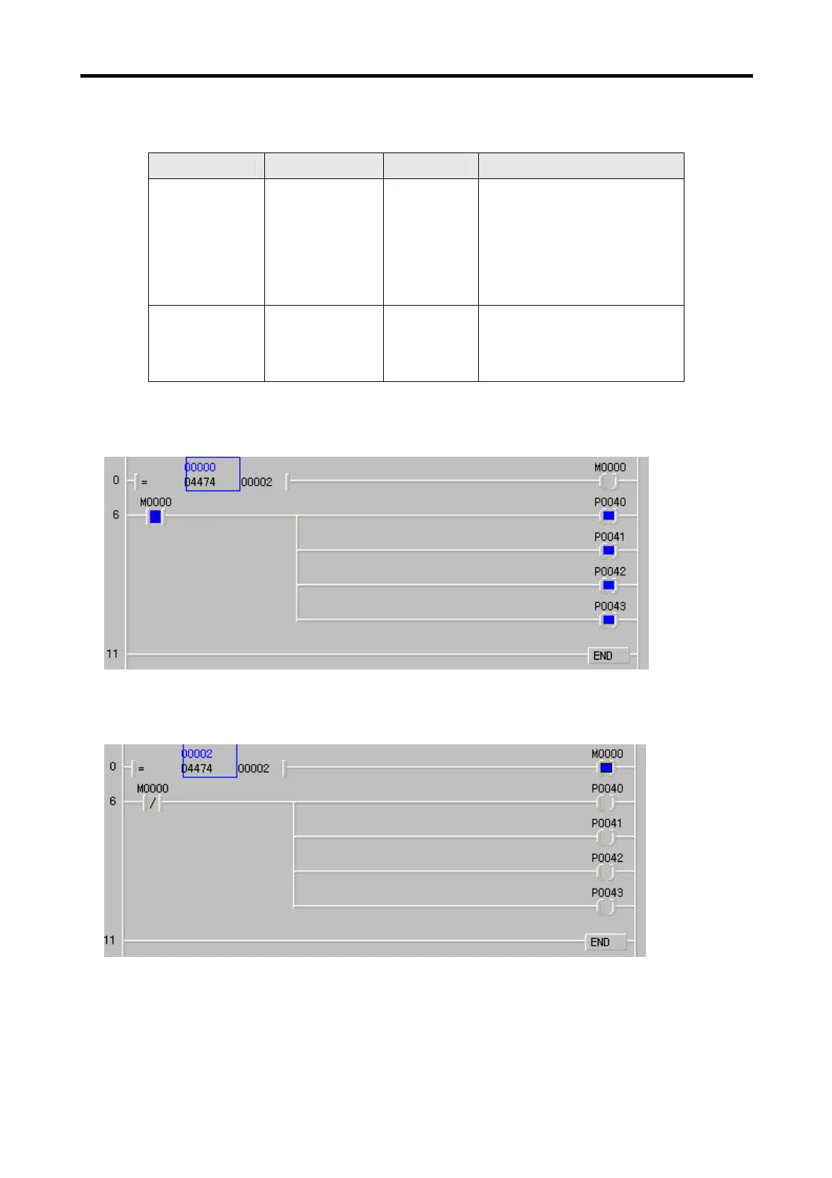
2) Make out following program with the KGLWIN. In normal operation status without LV trip, all of the
P0040~P0043 contact point outputs are in ON status.
3) When inverter LV trip is triggered (the 2
nd
bit of the D4474 register in which the common area address
0x332 is registered is turned ON), the output from the P0000~P0040 points are turned OFF.
For a large capacity inverter, if the digital outputs of the PLC option must be isolated at the LV trip of the
inverter, the above described method can be used.
 Loading...