EasyManuals Logo

LSIS H100 Troubleshooting Manual

LSIS H100
45 pages
To Next Page IconTo Next Page
To Previous Page IconTo Previous Page
Page #39 background imageLoading...
Page #39 background image
3. Maintenance
38
Check Input/Output Module 3.1.4
How to check the diode module and IGBT module (5.5~30kW)
Testing method
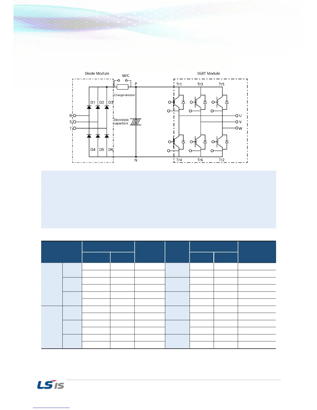
1) Disconnect all power cables (R,S,T) and motor output cables (U,V,W).
2) Before testing, check the discharge of electrolytic capacitor (DCP-DCN).
3) When the circuit is open, DMM will indicate high resistance (several M). In some situations, the DMM
may display a closed circuit (low resistance) and then show high resistance due to the capacitors.
When the circuit is closed, the DMM shows resistance of several hundred k or less.
4) Displayed values may not be constant as it depends on the module and tester type. The value
measured between the phases is acceptable if the standard deviation is approximately ±10%.
Module
Test Polarity
Check Value
Module
Test Polarity
Check Value
+
-
+
-
Diode
D1
R
P
Closed
D4
R
N
Open
P
R
Open
N
R
Closed
D2
S
P
Closed
D5
S
N
Open
P
S
Open
N
S
Closed
D3
T
P
Closed
D6
T
N
Open
P
T
Open
N
T
Closed
IGBT
Tr1
U
P
Closed
Tr4
U
N
Open
P
U
Open
N
U
Closed
Tr3
V
P
Closed
Tr6
V
N
Open
P
V
Open
N
V
Closed
Tr5
W
P
Closed
Tr2
W
N
Open
P
W
Open
N
W
Closed

Other manuals for LSIS H100

Questions and Answers:

Question and Answer IconNeed help?

Do you have a question about the LSIS H100 and is the answer not in the manual?

LSIS H100 Specifications

General IconGeneral
BrandLSIS
ModelH100
CategoryInverter
LanguageEnglish

Related product manuals