EasyManua.ls Logo

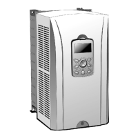
LSIS SV022iG5A-2 User Manual

LSIS SV022iG5A-2
181 pages
To Next Page IconTo Next Page
Page #1 background imageLoading...
Page #1 background image

Table of Contents

Questions and Answers:

LSIS SV022iG5A-2 Specifications

General IconGeneral
ModelSV022iG5A-2
TypeInverter
Frequency50/60Hz
SeriesiG5A
Control MethodV/F Control, Sensorless Vector Control
Cooling MethodForced Air Cooling
Enclosure RatingIP20
Rated Power (HP)3
Output Frequency0-400Hz
Protection FeaturesOvercurrent, Overvoltage, Overheat, Undervoltage
Operating Temperature-10°C to +50°C
Storage Temperature-20 ~ 65°C
Humidity5 to 95% RH (non-condensing)
AltitudeUp to 1000m
Rated Power (kW)2.2 kW
Input Voltage200 ~ 240 VAC
Phase3-phase

Summary

SAFETY INSTRUCTIONS

WARNING

Identifies potential hazards under certain conditions. Read the message and follow the instructions carefully.

CAUTION

Improper operation may result in slight to medium personal injury or property damage.

OPERATING PRECAUTIONS

(1) Handling and installation

Procedures and guidelines for safely handling and installing the inverter.

(2) Wiring

Instructions and precautions related to connecting power and control wires.

CHAPTER 1 - BASIC INFORMATION & PRECAUTIONS

1.1 Important precautions

Essential precautions for unpacking, inspection, and initial handling of the inverter.

CHAPTER 2 - INSTALLATION & WIRING

2.1 Installation precautions

Critical guidelines for safe and optimal inverter installation, including environmental factors.

2.3 Terminal wiring (Control I/O)

Details the connections and functions of the control input/output terminals.

CHAPTER 3 - BASIC CONFIGURATION

3.1 Connection of peripheral devices to the inverter

Explains how to connect essential peripheral devices for inverter operation.

CHAPTER 4 - PROGRAMMING KEYPAD & BASIC OPERATION

4.1 Keypad features

Details the functions of the inverter's keypad buttons and display indicators.

4.5 Parameter setting

Step-by-step guide on how to adjust parameter values in the inverter's Drive Group.

4.7 Frequency Setting and Basic Operation

Describes how to set frequency using keypad and terminals.

CHAPTER 7 - BASIC FUNCTIONS

7.3 Operating command setting method

Describes methods for controlling inverter operation via keypad or terminals.

7.4 Accel/Decel time and pattern setting

How to set acceleration, deceleration times, and S-curve patterns.

7.5 V/F control

Explains the different V/F control patterns for motor speed and voltage regulation.

7.6 Stop method select

How to configure the inverter's stopping behavior, including deceleration and DC braking.

7.7 Frequency limit

How to set maximum and minimum operating frequency limits.

CHAPTER 8 - ADVANCED FUNCTIONS

8.1 DC brake

Details the DC braking function for stopping the motor.

8.2 Jog operation

How to configure and perform low-speed jog operation of the motor.

8.7 PID control

Setup and configuration for Proportional-Integral-Derivative control loops.

8.8 Auto-tuning

Automatic measurement of motor parameters for optimal performance.

8.9 Sensorless Vector Control

Enables high-performance motor control without a speed sensor.

8.11 Speed search

Function to detect motor speed during startup or power interruptions.

8.25 Parameter Initialize / Lock

Resets parameters to factory defaults or locks them for security.

CHAPTER 9 - MONITORING

CHAPTER 10 - PROTECTIVE FUNCTIONS

10.1 Electronic Thermal

Protects the motor from overheating based on thermal load estimation.

CHAPTER 11 - RS485 COMMUNICATION

11.8 Troubleshooting

Guidance for resolving RS-485 communication errors.

CHAPTER 12 - TROUBLESHOOTING & MAINTENANCE

12.1 Protective functions.

Lists protective functions and corresponding keypad displays and descriptions.

12.2 Fault remedy

Provides solutions for common inverter faults displayed on the keypad.

12.3 Precautions for maintenance and inspection

Safety warnings and essential checks before performing maintenance.

CHAPTER 13 - SPECIFICATIONS

Protective function

Lists various protection functions including over/under voltage and over current.

RECOMMENDED INSTALLATION INSTRUCTIONS

Related product manuals