10-6
10.6 Inverter Overload
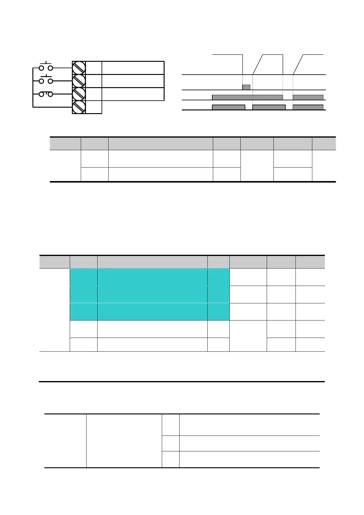
Group Code Parameter Set Range Initial Unit
I/O
group
I54
[Multi-function output terminal
select]
6
0 ~ 19
12
I55 [Multi-function relay select] 6 17
Inverter overload prevention function is activated when the current above inverter rated current
flows.
Multi-function output terminal (MO) or Multi-function relay (3ABC) is used as the alarm signal
output during inverter overload trip.
10.7 Speed command loss
Group Code Parameter Set Range Initial Unit
I/O
group
I16
[Select criteria for analog speed
command loss]
0
0 ~ 2 0
I62
[Drive mode select at loss of
speed command]
-
0 ~ 2 0
I63
[Wait time after loss of speed
command]
-
0.1 ~ 120 1.0 sec
I54
[Multi-function output terminal
select]
11
0 ~ 19
12
I55
[Multi-function relay select]
11 17
Select the Drive mode when frequency reference set via Analog (V1, I) input terminal or
communication option is lost.
I16: This is to set the criteria for analog input signal loss.
I16 [Criteria for analog
input signal loss]
0
Disabled (Does not check the analog input
signal loss)
1
When half the value set in I2, I7, I12 is
entered
2
When less than the value set in I 2, I 7, I 12
is entered
P1
P7
P8
FX : I17 = 0
N.O. : I23 = 18
CM
N.C. : I24 = 19
P4(A contact)
Frequency
Run
command
P5(B contact)
 Loading...


