8-19
8.13 Operating sound select (Carrier frequency change)
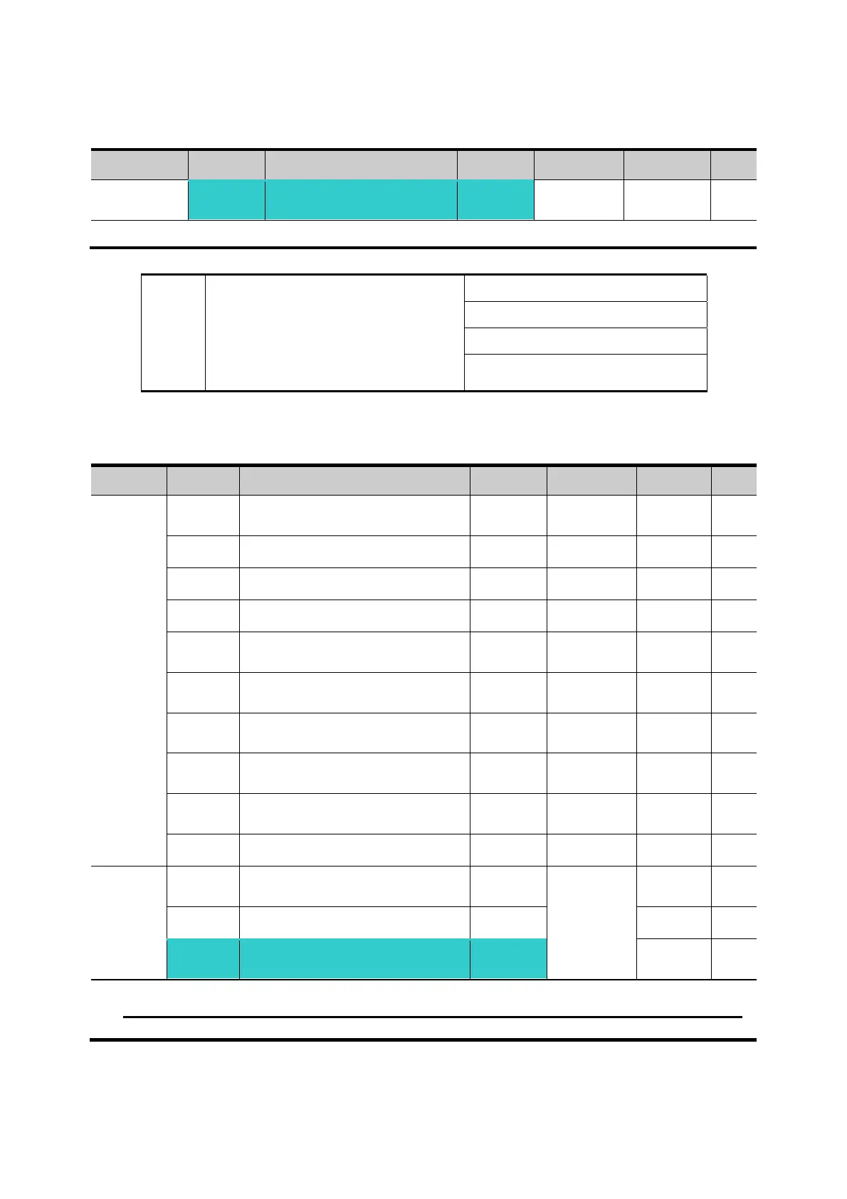
Group Display Parameter Name Setting Range Default Unit
Function
group 2
H39 [Carrier frequency] -
1 ~ 15 3 kHz
This parameter affects the sound of the inverter during operation.
H39 When setting carrier frequency
high,
Motor sound reduced
Inverter heat loss increased
Inverter noise increased
Inverter leakage current
increased
8.14 2
nd
motor operation
Group Display Parameter Name Setting Range Default Unit
Function
group 2
H81 [2nd motor accel time] - 0 ~ 6000 5.0 sec
H82 [2nd motor decel time] -
0 ~ 6000
10.0 sec
H83 [2nd motor base freq.] - 30 ~ 400 60.00 Hz
H84 [2nd motor V/F pattern] - 0 ~ 2 0
H85
[2nd motor Positive torque
boost]
- 0 ~ 15 5 %
H86
[2nd motor Negative torque
boost]
- 0 ~ 15 5 %
H87
[2nd motor stall prevention
level]
- 30 ~ 150 150 %
H88
[2nd motor electronic thermal
level for 1 min]
- 50 ~ 200 150 %
H89
[2nd motor electronic thermal
level for continuous operation]
- 50 ~ 150 100 %
H90 [2nd motor rated current] - 0.1~100 26.3 A
I/O
group
I17
[Multi-function Input terminal
P1Function select]
-
0 ~ 27
0
~ ~
I24
[Multi-function Input
terminal P8Function select]
12
7
Set the terminal among Multi-function input P1 thru P5 for second motor operation.
To define the terminal P5 as second motor operation, set I24 to 12.
 Loading...


