EasyManuals Logo

LSIS H100 Troubleshooting Manual

LSIS H100
45 pages
To Next Page IconTo Next Page
To Previous Page IconTo Previous Page
Page #41 background imageLoading...
Page #41 background image
3. Maintenance
40
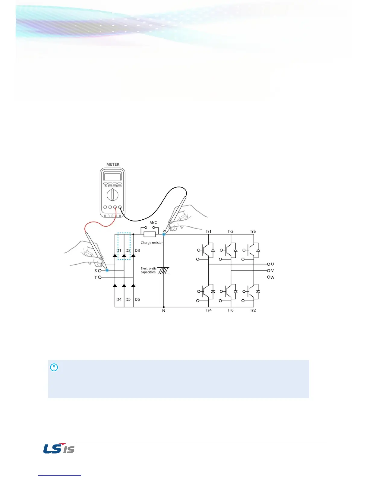
Example) Checking diode module and IGBT module
Checking Diode D2
1) Measure the resistance of D2 by placing the red lead (positive terminal of DMM) on S phase
and the black lead (negative terminal of DMM) on P.
If the resistance indicated on DMM is several hundred kΩ or less, it is acceptable.
2) Measure the resistance of D2 by placing the red lead from the positive terminal of DMM on P
and the black lead from negative terminal of DMM on S phase.
If the resistance indicated on DMM is M, it is acceptable.
3) Measure the resistance of other diodes in the same way.
Caution
Before testing, check the discharge of electrolytic capacitor (DCP-DCN).

Other manuals for LSIS H100

Questions and Answers:

Question and Answer IconNeed help?

Do you have a question about the LSIS H100 and is the answer not in the manual?

LSIS H100 Specifications

General IconGeneral
BrandLSIS
ModelH100
CategoryInverter
LanguageEnglish

Related product manuals