4.4 Command Source Configuration
Various devices can be selected as command input devices for the G100 inverter.
Input devices available to select include keypad, multi-function input terminal, RS-485
communication and field bus adapter.
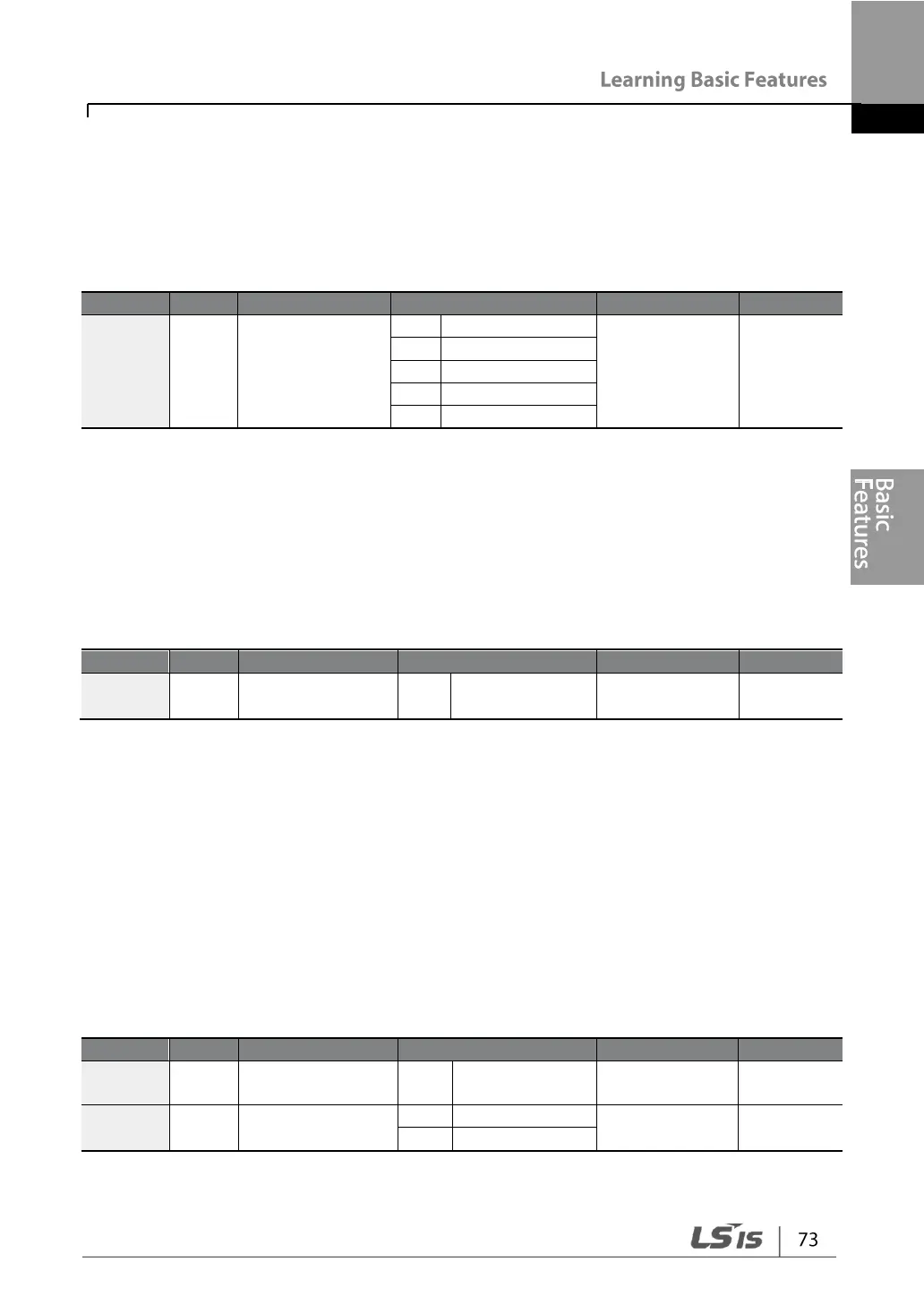
4.4.1 The Keypad as a Command Input Device
The keypad can be selected as a command input device to send command signals to
the inverter. This is configured by setting the drv (command source) code to 0
(Keypad). Press the [RUN] key on the keypad to start an operation, and the
[STOP/RESET] key to end it.
4.4.2 Terminal Block as a Command Input Device (Fwd/Rev
Run Commands)
Multi-function terminals can be selected as a command input device. This is
configured by setting the drv (command source) code in the Operation group to 1
(Fx/Rx-1). Select terminals for the forward and reverse operations from P1–P5 multi-
function input terminals. Then select 1 (Fx) and 2 (Rx) respectively for 65–69 (Px
terminal setting options) codes of the In group. This enables both terminals to be
turned on or off at the same time, constituting a stop command that will cause the
inverter to stop operation.
Px terminal
setting options

 Loading...