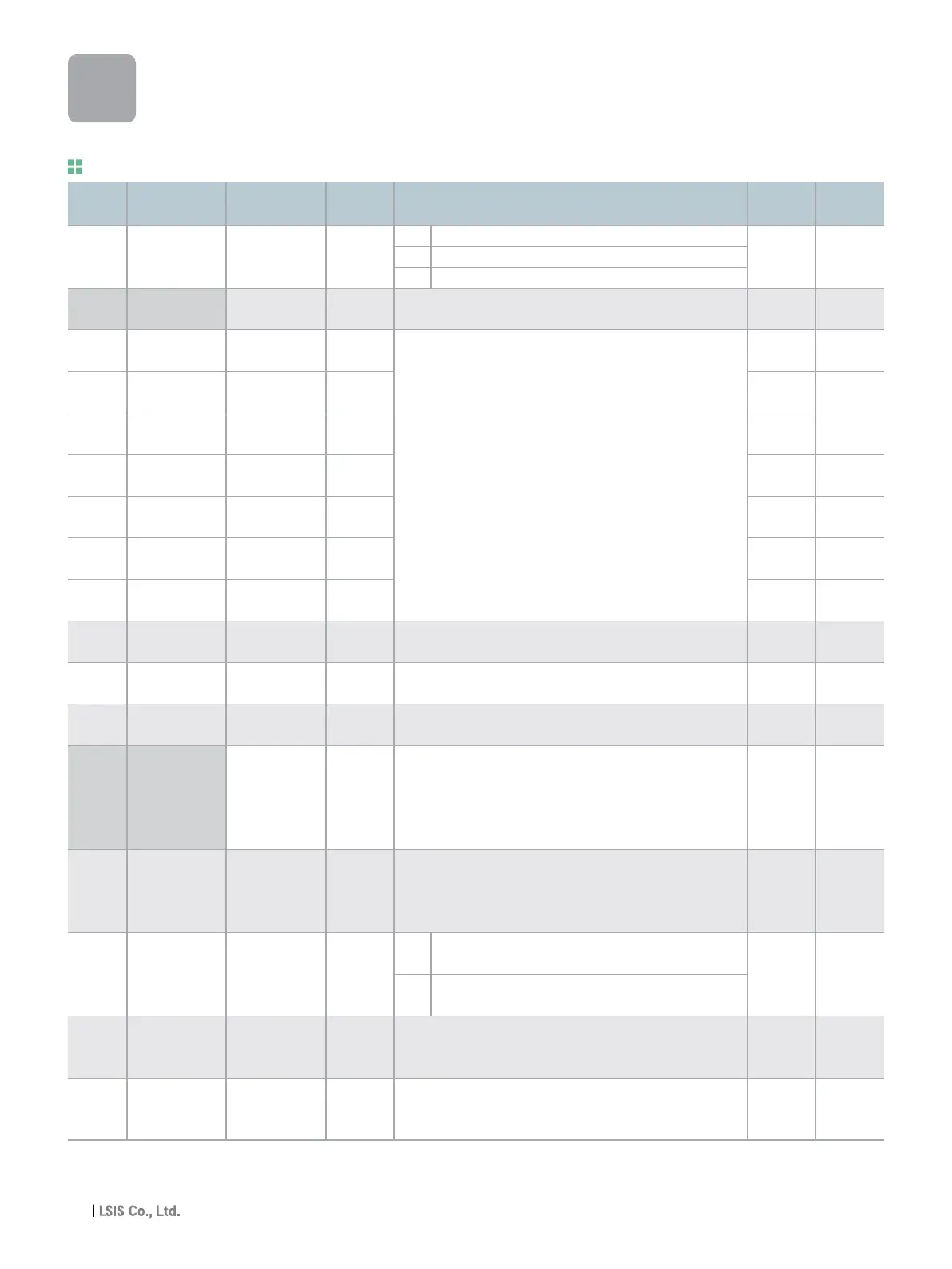
1) Set F30 to 2(User V/F) to display this parameter.
2) Set F50 to 1 to display this parameter.
LED
display
Address for
communication
Parameter
name
Min/Max
range
Description
Adj.
during run
Factory
defaults
Function group 1
A21E [V/F pattern] 0 ~ 2
A21F
[User V/F 0 ~ 400
frequency 1] [Hz]
A220
[User V/F ] 0 ~ 100
voltage 1 [%]
A221
[User V/F 0 ~ 400
frequency 2] [Hz]
A222
[User V/F 0 ~ 100
voltage 2] [%]
A223
[User V/F 0 ~ 400
frequency 3] [Hz]
A224
[User V/F 0 ~ 100
voltage 3] [%]
A225
[User V/F 0 ~ 400
frequency 4] [Hz]
A226
[User V/F 0 ~ 100
voltage 4] [%]
A227
[Output voltage 40 ~ 110
adjustment] [%]
A228
[Energy-saving 0 ~ 30
level] [%]
A232
[Electronic
0 ~ 1
thermal select]
[Electronic
50 ~ 200
A233 thermal level for
[%]
1 minute]
[Electronic
50 ~ 150
A234 thermal level for
[%]
continuous]
A235
[Motor cooling
0 ~ 1
method]
[Overload 30 ~ 150
A236
warning level] [%]
[Overload 0 ~ 30
A237
warning time] [Sec]
0 {Linear}
1 {Square}
2 {User V/F}
It is used only when V/F pattern is set to 2(User V/F)
It cannot be set above F21 - [Max frequency].
The value of voltage is set in percent of H70 - [Motor rated
voltage].
The values of the lower-numbered parameters cannot be set
above those of higher-numbered.
This parameter adjusts the amount of output voltage.
The set value is the percentage of input voltage.
This parameter decreases output voltage according to load
status.
This parameter is activated when the motor is overheated (time-
inverse).
This parameter sets max current capable of flowing to the motor
continuously for 1 minute.
The set value is the percentage of H33 - [Motor rated current].
It cannot be set below F52 - [Electronic thermal level for
continuous].
This parameter sets the amount of current to keep the motor
running continuously.
It cannot be set higher than F51 - [Electronic thermal level for 1
minute].
0
Standard motor having cooling fan directly connected to
the shaft
1 A motor using a separate motor to power a cooling fan.
This parameter sets the amount of current to issue an alarm
signal at a relay or multi-function output terminal (see I54, I55).
The set value is the percentage of H33- [Motor rated current].
This parameter issues an alarm signal when the current greater
than F54- [Overload warning level] flows to the motor for F55-
[Overload warning time].
0 X
15.00 X
25 X
30.00 X
50 X
45.00 X
75 X
60.00 X
100 X
100 X
0 0
0 0
150 0
100 0
0 0
150 0
10 0
F30
F31
F32
F33
F34
F35
F36
F37
F38
F39
F40
F50
F51
F52
F53
F54
F55
2)
iG5A
Function List
1)
28

 Loading...
