1) only displayed when H10 is set to 1. # H17, H18 are used when F2, F3 are set to 1 (S-curve)
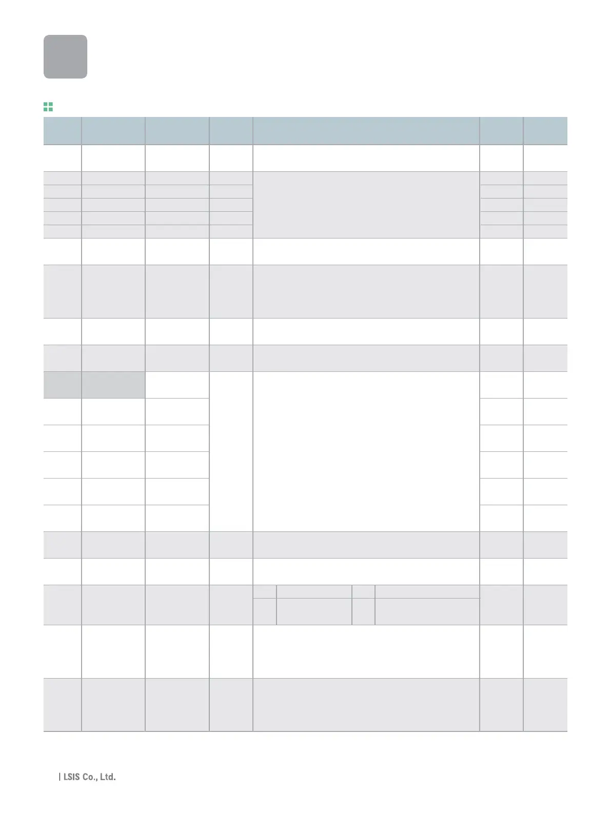
LED
display
Address for
communication
Parameter
name
Min/Max
range
Description
Adj.
during run
Factory
defaults
Function group 2
A300 [Jump code] 0~95
A301 [Fault history 1] -
A302 [Fault history 2] -
A303 [Fault history 3] -
A304 [Fault history 4] -
A305 [Fault history 5] -
A306
[Reset fault
0~1
history]
A307 [Dwell frequency]
0.1~400
[Hz]
A308 [Dwell time] 0~10 [sec]
A30A [Skip frequency 0 ~ 1
select]
A30B
[Skip frequency
low limit 1]
A30C
[Skip frequency
high limit 1]
A30D
[Skip frequency
low limit 2] 0.1~400
A30E
[Skip frequency [Hz]
high limit 2]
A30F
[Skip frequency
low limit 3]
A310
[Skip frequency
high limit 3]
A311
[S-Curve accel/ 1~100
decel start side] [%]
A312
[S-Curve accel/ 1~100
decel end side] [%]
[Input/output
A313 phase loss 0 ~ 3
protection select]
A314
[Power On
0 ~ 1
Start select]
[Restart after
A315 fault reset 0 ~1
selection]
Sets the code number to jump.
Stores information on the types of faults, the frequency, the
current and the Accel/Decel condition at the time of fault. The
latest fault is automatically stored in the H 1- [Fault history 1].
Clears the fault history saved in H 1-5.
When run frequency is issued, motor starts to accelerate after
dwell frequency is applied to the motor during H8- [Dwell time].
[Dwell frequency] can be set within the range of F21- [Max
frequency] and F23- [Start frequency].
Sets the time for dwell operation.
Sets the frequency range to skip to prevent undesirable
resonance and vibration on the structure of the machine.
Run frequency cannot be set within the range of H11 thru H16.
The frequency values of the low numbered parameters cannot
be set above those of the high numbered ones. Settable within
the range of F21 and F23.
Set the speed reference value to form a curve at the start during
accel/decel. If it is set higher, linear zone gets smaller.
Set the speed reference value to form a curve at the end during
accel/decel. If it is set higher, linear zone gets smaller.
This parameter is activated when drv is set to 1 or 2 (Run/Stop
via Control terminal).
Motor starts acceleration after AC power is applied while FX or
RX terminal is ON.
This parameter is activated when drv is set to 1 or 2 (Run/Stop
via Control terminal).
Motor accelerates after the fault condition is reset while the FX or
RX terminal is ON.
1 O
nOn -
nOn -
nOn -
nOn -
nOn -
0 O
5.00 X
0.0 X
0 X
10.00 X
15.00 X
20.00 X
25.00 X
30.00 X
35.00 X
40 X
40 X
0 O
0 O
0 O
H 0
H 1
H 2
H 3
H 4
H 5
H 6
H 7
H 8
H10
H11
H12
H13
H14
H15
H16
H17
H18
H19
H20
H21
0 Disabled 1 Output phase protection
2
Input phase
3
Input/output phase
protection protection
iG5A
Function List
1)
30

 Loading...
