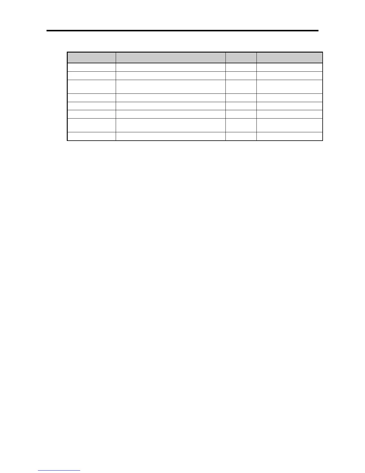
Position Sync. Position synchronization reference signal BIT -
Indirect start Main axis indirect start reference signal BIT -
%KX6880
Sub-axis (Y-
BIT -
%KX6881 Sub-axis (Y-axis) in error state BIT -
%KX6724 X-axis reference determined state BIT -
%KX6884 Y-axis reference determined state BIT -
%KX6720
Main axis (X-
BIT -
%KX6721 Main axis (X-axis) in error state BIT -
(c) Program Operation
•At the rising edge of the ‘position synchronization’ signal used as the position synchronization
reference signal, APM_SSP instruction is executed.
At this time, since the AXIS is 1 (Y-axis), Y-axis is the sub-axis and as the MST_AXIS is 0 (X-axis),
X-axis is the main axis.
•At the rising edge of the ‘indirect start-up’ signal which is the indirect start-up reference signal of the
main axis, No. 1 step of the X-axis starts indirectly.
•During operation, when the present position of the main axis reaches 100,000 [Pulse] set up in the
MAST_ADDR of the APM_SSP instruction, the Y-axis which is the sub-axis starts up the operation
step (No. 1) set up in the STEP of the APM_SSP instruction.