36
General Operation: Automated Lubrication System
(ALS) – Pump Mounted Timer
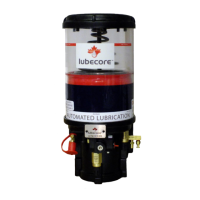
The Lubecore™ Automated Lubrication System (ALS) can be equipped with several options
and a variety of pump styles. This section describes the general operation of a standard
pneumatic lubrication pump with standard components and a pump mounted timer which may
be used on any equipment but is particularly useful for trailer applications. For details regarding
the operation of our other pumps and components, please refer to the appropriate Lubecore
manual or contact Lubecore directly. A Lubecore automated lubrication system consists of the
following main components.
Note: The ① are identification markers referring to items in Error! Reference source not
found..
- ① Pneumatically operated pump.
- ② Pump Mounted Timer connected to pump solenoid.
- ③ Manifold and ④ injector assemblies.
- ⑤ Primary and ⑥ secondary tubing with ⑨ fittings.
A Lubecore parallel automated lubrication system will be designed and assembled according to
the specific type of equipment and the associated operating conditions. Starting with the
manufacturer specifications regarding the lubrication requirement, the system layout will be
designed and the appropriate components will be selected.
The pump mounted timer ② has been designed to operate using a minimal amount of current
and still provide the full option functionality of performance and low-level monitoring ⑦. When
mounted on a trailer, the timer could use the following power sources:
1) Constant power: ABS (Anti-lock Braking System)
2) Junction box/nose plug: Brake, indicator and running lights using a diode bridge.
3) Rechargeable power supply module.
As long as the trailer is in use, the timer ② will perform its programmed function. Once it
reaches the end of the interval, the timer engages the solenoid and the green sequential LED
mounted in the timer enclosure starts a chase pattern indicating the pump is in cycle. The
activation of the solenoid provides the pump ① with air pressure from the air tank ⑧.
In turn the pump ① pumps the maximum allowable amount of grease, under pressure, into the
mainline tubing ⑤ that connects the pump front the mainline fitting ⑪ to either one or more
manifolds ③, which are located at centralized points along the trailer.
The moment maximum pressure is reached in the mainline tubing ⑤, injectors ④ located in the
manifolds begin to measure and dispense a predetermined and consistent amount of lubricant
through the secondary tubing ⑥ and fittings ⑨ and into the lubrication points ⑩.
At completion of the lubrication cycle, the solenoid is deactivated by the timer, air in the pump is
released, grease chamber is replenished with grease and the timer begins counting down
toward its next lubrication cycle.