Lucent Technologies Lineage
®
2000 ECS Battery Plant J85500D-3
4 - 4 Installation Issue 5 January 1999
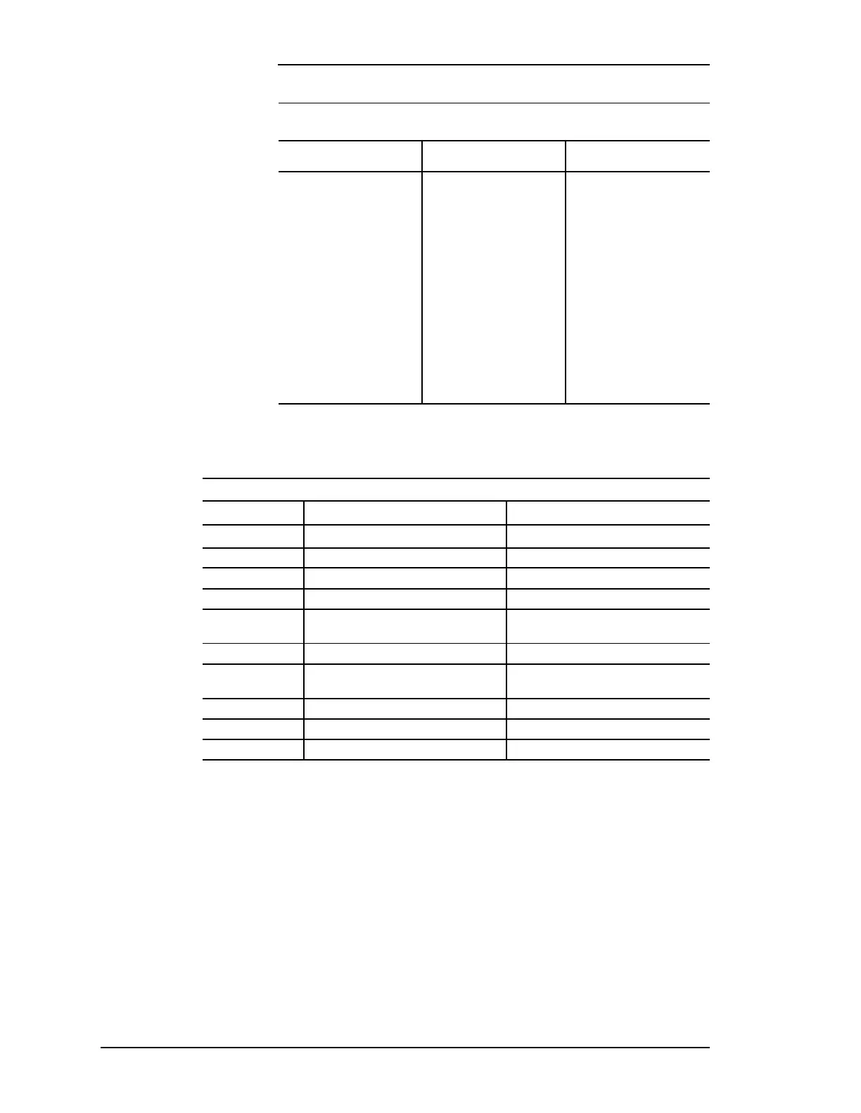
Sequence of tasks Table4-C lists the drawings, manuals and other documentation
that are necessary to complete the following Sequence of Tasks.
Step A:
Unpacking,
handling &
frame installation
Before opening the packaging, carefully inspect the outside, in
the presence of shipping personnel, for signs of damage. If
damaged, follow the shipping carrier's procedure for filing a
damage claim.
Table 4-B: Torque And Minimum Yield Strength For
Mechanical Connections (Using Hex Head Cap Screws)
CAP SCREW DIAMETER
MINIMUM YIELD
STRENGTH (PSI)
TORQUE (FT-LB) UNRC
1/4
3/16
3/8
7/16
1/2
9/16
5/8
3/4
7/8
1
R1-1/8
1-1/4
1-3/8
1-1/2
57,000
57,000
57,000
57,000
57,000
57,000
57,000
57,000
36,000
36,000
36,000
36,000
36,000
36,000
6
12
22
35
54
77
107
190
193
290
410
580
760
1010
Table 4-C: Installation Reference
Documents
Step Procedure Reference Document
A Unpacking
J85500D-3 Manual (167-790-064)
B Battery Stand Assembly Battery Manual (157-622-010)
J85504C-1
C Cable Support and Ground System Job Application Drawings
D
Controller Setup and LVD Test
Controller Manual
E
AC Wiring, Rectifier Installation and
Rectifier Test
Rectifier Manual, J85500D-3 Drawing and
T-82670-30 Drawing
F Battery Connections Battery Manual
G Load Wiring
J85500D-3 Drawing and T-82670-30
Drawing
H Initial Battery Charge Battery Manual andRectifier Manual
I Controller Test Controller Manual
J Load Turn Up Load Equipment Documentation