Lucent Technologies Lineage
®
2000 ECS Battery Plant J85500D-3
Issue 5 January 1999 Installation 4 - 9
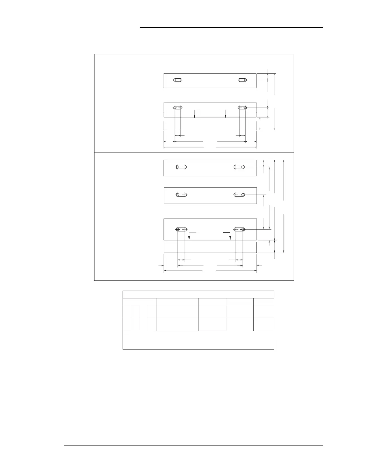
Figure 4-2: Floor mounting template, VR battery installation
(all dimensions are given in inches)
C1
B1
A1
C1
B1
A1
FRONT
2.00 2.00
3.85 3.85
3.5 REF
3.00
9.66
17.39
22.39
25.90*
2.00
18.20
25.90*
C2
B2
A2
C2
B2
A2
* Overall Dimension including
Retainers and Covers
* Overall Dimension including
Retainers and Covers
Foot Print for Lists 31, 32, 43, 44
(See Floor Anchor Loc. Table)
Foot Print for Lists 1, 2, 41, 42
(See Floor Anchor Loc. Table)
Fig. A
Fig. B
25.90 *
18.20 3.85
2.00
3.85
2.00
A2A2 A1A1
3.50
REF
3.00
18.17 *
9.66
2.00
B2B2B1 B1
FRONT
Floor Anchor Location Table
List
31
1
32
2
43
41
44
42
A1, B1
A1, B1, C1
A2, B2
A2, B2, C2
A
B
2VR250E
Battery Application
2VR375E
Battery Application
Description Primary Alternate** Figure
** If interference with floor reinforcing bars occurs during
installation of anchoring device at primary mounting location
then alternate location shall be used.