IGA 320/23-LO Operating Manual Controls and Connections
15
3.2.2 Wait time t
w
When using a pyrometer with RS485, it is possible that the connection is not fast enough to
receive the pyrometer’s answer to an instruction of the master. In this case, a wait time
(between 00 and 99 bit) can be set to slow down the data transfer (e.g.: t
w
= 02 at a baud rate
9600 means a wait time of
2
/
9600
sec).
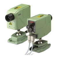
3.2.3 Connecting additional analyzing devices
Additional analyzing instruments, such as a LED digital display instrument, need to be connected
to a power supply and the analog outputs from the pyrometer. Other instruments, like a
controller or printer, can be connected to the display in series as shown below (total load of
resistance max. 500 Ohm).
3.3 Mechanical Installation
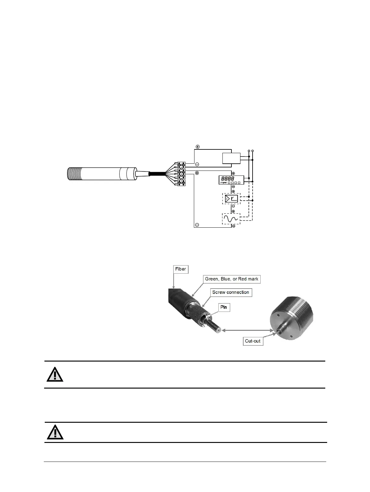
3.3.1 Fiber optic
The fiber has either a green mark
(MB 6) blue mark (MB 7) or a red mark
(MB 12) for correct connection to the
pyrometer. This color mark has to be
mounted on the pyrometer’s side.
Please note that the connector on the
instrument side of the fiber has an
alignment pin. When connecting to
the socket, you have to turn the
connector until the pin is in the right
orientation before you can fix the
connector with the knurled nut.
Attention: The light guide end of the fiber optic cable as well as the
socket/connector and the optical head must always be protected with the caps when
not connected!
Ambient temperature
The fiber and optical head can withstand ambient temperatures up to 200 °C without cooling on
the side of the optical head.
Attention: The temperature of the fiber and optical head must be at least 30 °C
lower than the measuring temperature to get a correct temperature reading.

 Loading...