IGA 320/23-LO Operating Manual Controls and Connections
13
3 Controls and Connections
3.1 Electrical Installation
The IGA 320/23-LO is powered by a voltage of 24 V DC (possible range 10 to 30 V, ripple < 0.5 V).
It is important to ensure correct polarity when connecting the device to the power supply.
To meet the electromagnetic requirements (EMV), a shielded connecting cable must be used.
LumaSense offers connecting cables, which are not part of the standard scope of delivery. The
shield of the connecting cable has to be connected only on the pyrometer’s side. If the
connecting cable is extended, the shield of the extension also needs to be extended. The shield
must be open on the power supply side (switchboard), to avoid ground loops.
The connecting cable has wires for the power supply, interface, analog output, switch contact,
and external clearing of the maximum value storage via contact and 8-pin connector (see
Chapter 8
, Reference numbers).
Warning: Follow common safety regulations for mains voltage (230 or 115 V AC) and
connecting additional devices operating with this mains voltage (e.g. transformers).
Touching mains voltage can be fatal. A non-expert connection and mounting can
cause serious health or material damages.
Only qualified specialists are allowed to connect such devices to the mains voltage.
Once the instrument has been connected to the power supply, it is immediately ready for use.
Although it does not need to be warmed up, it does need to run for approximately 15 to 30
minutes before achieving full accuracy. The instrument can be switched off by interrupting the
power supply or unplugging the electrical connector.
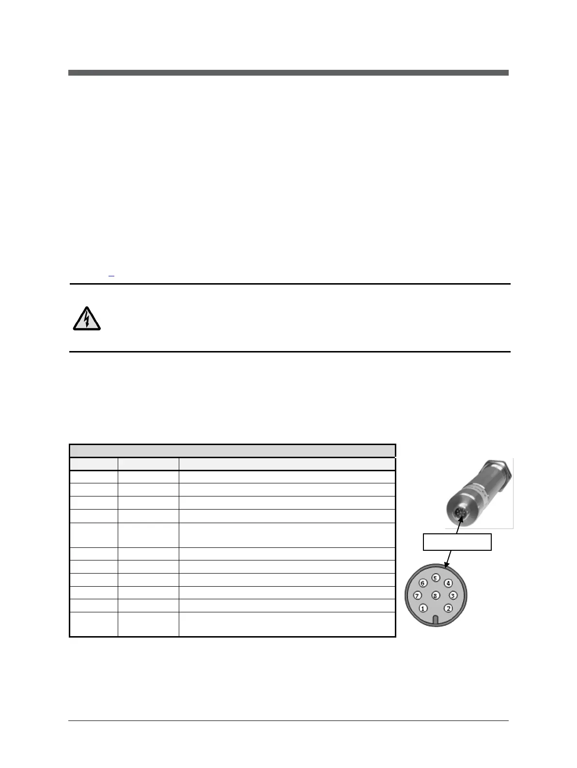
3.1.1 Pin assignment of the male socket on the back of the pyrometer
3 green
5 grey
Switches on and off LED targeting light
(via push button) (bridge to +24 V)
switch contact (reference point 0 V)
orange
Screen only for cable extension,
don’t connect at the switchboard
(side of male
inserts)

 Loading...