INSTALLATION
10 to 30 VDC
Switches can be placed on input OR output (one side only)
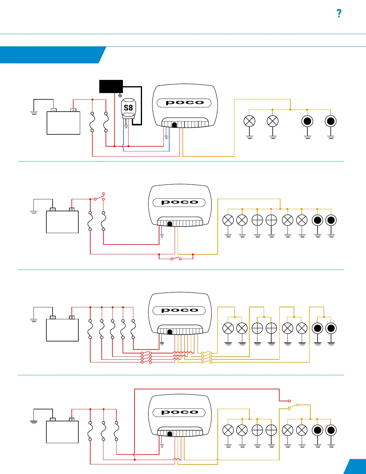
Fig. 5
10 A 3 A10 A 10 A 10 A
1-IN
1-OUT
2-IN
2-OUT
3-IN
3-OUT
4-IN
4-OUT
LAN
ACC
GRND
PWR
Fig. 6: Use of an SPST switch on each channel to allow for standard Lumitec TTP control as well as digital PLI control (non-redundant)
Note: POCO will need to be congured with startup commands to turn on all 4 channels by default. Refer to “Startup Switch” under Automation section.
continued...
Fig. 5: Use of an SPST switch on a channel to allow for redundant mechanical control of a set of lights within the system allowing for
standard Lumitec TTP control or Poco digital PLI control
10 to 30 VDC
Fig. 4
10 A 3 A
1-IN
1-OUT
2-IN
2-OUT
3-IN
3-OUT
4-IN
4-OUT
LAN
ACC
GRND
PWR
Switch must be in open position for Poco operation
Manual Mode/TTP
Poco Mode/Digital
10 to 30 VDC
Fig. 6
10 A 3 A10 A
1-IN
1-OUT
2-IN
2-OUT
3-IN
3-OUT
4-IN
4-OUT
LAN
ACC
GRND
PWR
Poco
TTP
OFF X
Fig. 7: Use of an SPDT switch prior to all lighting circuits to allow for redundant mechanical control of entire lighting system with one switch
SWITCH
PANEL
10 to 30 VDC
Fig. 7
10 A 3 A
1-IN
1-OUT
2-IN
2-OUT
3-IN
3-OUT
4-IN
4-OUT
LAN
ACC
GRND
PWR
Fig. 4: Use of a Lumitec Pico S8 module to allow POCO to read the state of mechanical switches and send corresponding digital commands to lights.
10