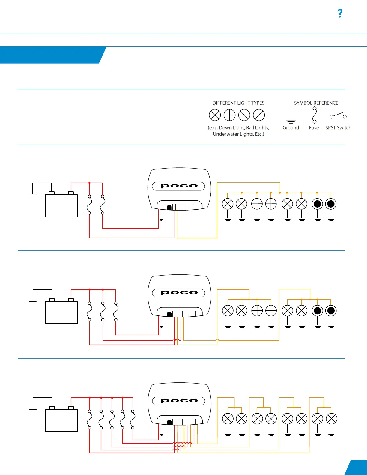
10 to 30 VDC
Fig. 3
10 A 3 A10 A 10 A 10 A
1-IN
1-OUT
2-IN
2-OUT
3-IN
3-OUT
4-IN
4-OUT
LAN
ACC
GRND
PWR
INSTALLATION
These schematics are intended to be used as general guidelines. Wiring
requirements will vary from vessel to vessel.
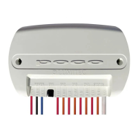
Note: The Pico S8 module provides the easiest way to connect mechanical
switches to your Poco 3 device. See Fig. 4 for wiring diagram.
Fig. 1: Use of a single channel to control multiple light types within the lighting system
Fig. 2: Use of different channels to allow isolated control of a set of similar light types within the system
Fig. 3: Use of different channels to allow isolated control of PLI and PWM lighting
Various System Configurations
Installation continued...
continued...
10 to 30 VDC
Fig. 1
10 A 3 A
1-IN
1-OUT
2-IN
2-OUT
3-IN
3-OUT
4-IN
4-OUT
LAN
ACC
GRND
PWR
10 to 30 VDC
Fig. 2
10 A 3 A10 A
1-IN
1-OUT
2-IN
2-OUT
3-IN
3-OUT
4-IN
4-OUT
LAN
ACC
GRND
PWR
09