SPECIFICATIONS
FEATURES INDICATOR DESCRIPTIONS
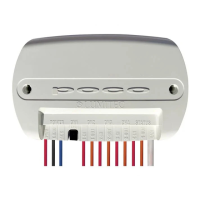
PWR Red Wire Positive 10-30 VDC POCO logic supply power. Line must be fused prior to connecting to POCO with
3 Amp ATC blade fuse or equivalent.
GRND Black Wire Supply Power Ground (Battery negative terminal).
ACC Blue Wire Poco Accesory Bus blue wire to connect to Pico S8 modules.
RESET Button See “RESET MODES” chart on page 6.
1-4 IN Red Wires Channel Input power. Line must be fused prior to connecting to POCO with 10 Amp ATC blade fuse
or equivalent (14 AWG 300V 16 inch long cable).
1-4 OUT Orange Wires Channel Output power to lighting circuit. Maximum 10 Amp load per channel. Maximum total load
across all channels is limited to 40 Amps. Load on channel must be only one of the following:
(Lumitec PLI enabled lighting/lighting capable of dimming (through PWM) / device requiring a
standard ON-OFF circuit). (14 AWG 300V 16 inch long cable).
LAN Ethernet Cable Local Area Network connection. 10/100 Base-T data connection to POCO. Standard CAT-5 cable
with RJ45 connector required to plug into sealed network cable adapter. (18 inch long cable with
Link light).
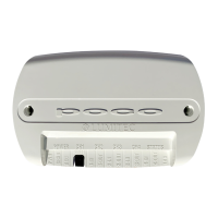
POCO STATUS LIGHTS
POWER Green Solid POCO is powered on
CH1-4 Red Solid Red if power is supplied to Channel from fuse/breaker panel.
Green Solid Channel has power on output wire.
Orange Flash PLI data is being transmitted.
Orange Solid Channel dimmed through a PWM.
Not Illiminated None No power to channel input (Check fuse/breaker).
STATUS Green 1 Flash WiFi enabled but not connected.
2 Flash WiFi is enabled and connected.
Blue 1 Flash Bluetooth enabled but not connected.
2 Flash Bluetooth enabled and connected.
Not Illuminated WiFi and Bluetooth disabled within Poco.
Features
continued...
Specications continued...
05