Hardware Connections
3.2.2 Connections to Equipment with 25-Pin AES/EBU D-Sub Connectors
The CBL-AES1603 and CBL-AES1605 breakout cables are provide 25-pin D-sub connections for industry
standard equipment. Refer to the table in Section 3.2 AES/EBU Cable Connections for equipment
compatibility information.
Connect the 26-pin high-density connecter on each cable to I/O Ports A and B. Connect the 25-pin D-sub
connector on each cable to the external device. Tighten the thumbscrews on the cable shells for a secure
connection.
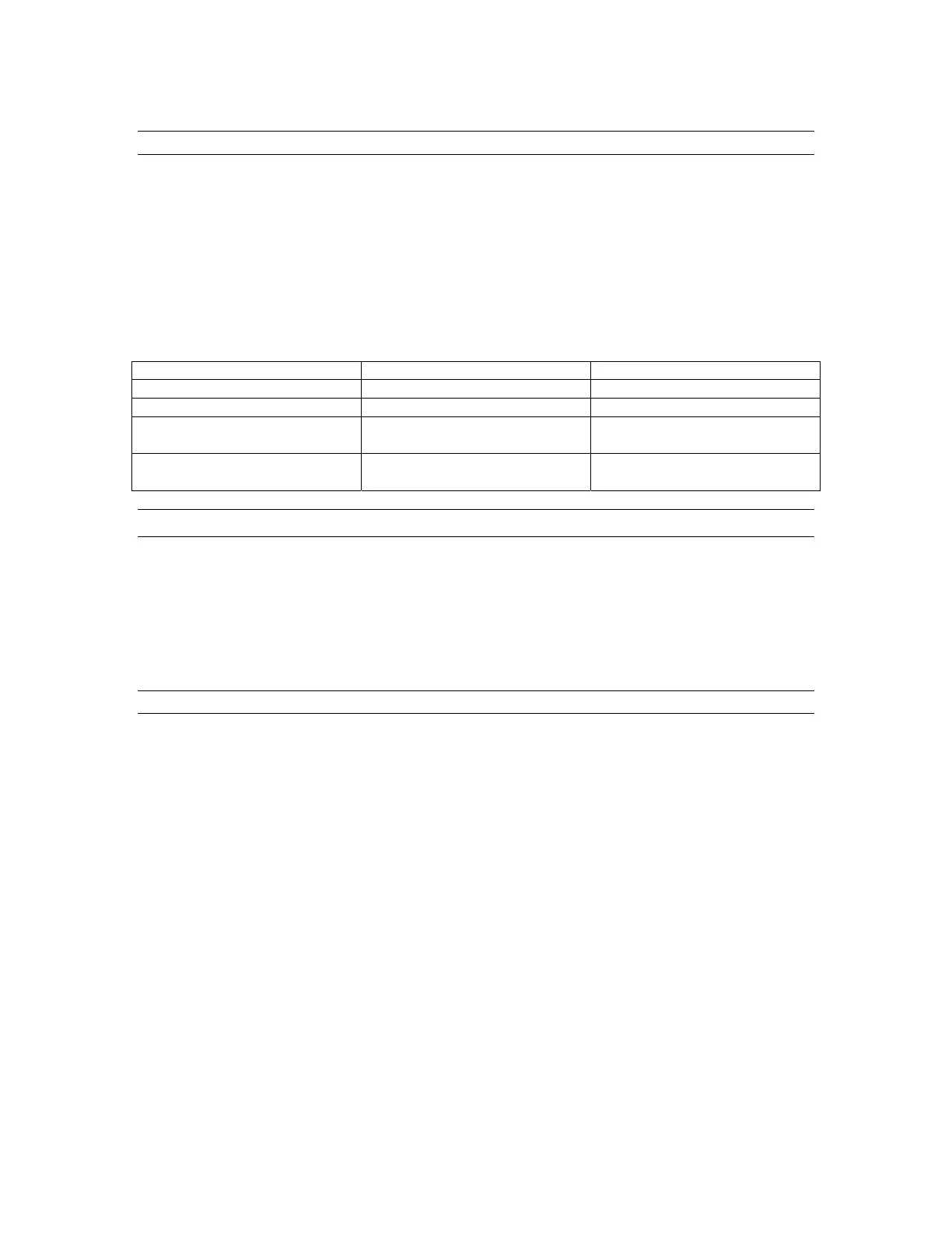
The signals associated with each 25-pin D-sub connector depend on which I/O Port on is used according to
the following table:
Lynx Cable Port Connected To Signals on 25-Pin D-sub
CBL-AES1603 I/O Port A DIGITAL IN 1-8
CBL-AES1603 I/O Port B DIGITAL OUT 1-8
CBL-AES1605 I/O Port A DIGITAL IN 1-4 and
DIGITAL OUT 1-4
CBL-AES1605 I/O Port B DIGITAL IN 5-8 and
DIGITAL 5-8
3.3 Clock Connections
In any system with more than one digital device, there can be only one master clock providing
synchronization. Whether you designate the AES16 as the clock master (slaving all other devices to it) or
slave the AES16 to another clock master, it is important that only a single device act as clock master, to
prevent the occurrence of audible digital errors.
The AES16 provides connections that allow for synchronization with external equipment or internal
devices within the computer.
3.3.1 External Clocking
Clock connections to external equipment are currently provided only with the CBL-AES1604 XLR
breakout cable. However, the AES16 can still be synchronized to external equipment using its AES/EBU
digital I/O.
With the CBL-AES1604 Cable connected to I/O Port A of the AES16, the BNC connector labeled
CLOCK acts a clock input. This input supports TTL signal levels and is terminated with 75 ohms of
impedance.
Connect this input to the clock output of an external device and select “External” as the Sample Clock
Source in the Lynx Mixer. Adjust the Sample Clock Reference to match the incoming clock type.
With the CBL-AES1604 Cable connected to I/O Port B of the AES16, the BNC connector labeled
CLOCK acts a word clock output. This output provides a 75-ohm TTL level signal at a frequency that
tracks the sample clock rate of the AES16. Connect this output to the word clock input of an external
device.
AES16 User Manual 26