Lynx Mixer Reference
6.4 Outputs Window
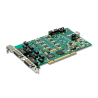
1^ Output Monitor Source Buttons
These buttons control the routing of record and playback sources that feed each of the 16 output channels.
Since each output is derived from the sum of the four sources, each button controls the selection of one of
the sources.
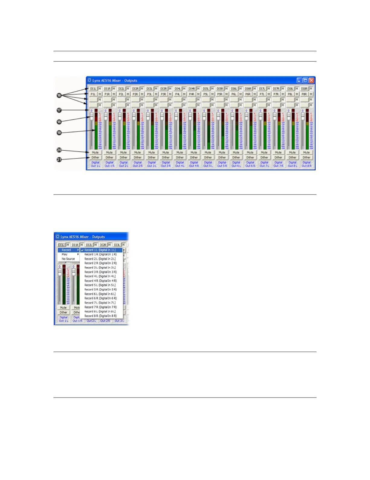
When a button is clicked, a pop-up menu is launched that displays the
available sources that can be selected. A Record submenu lists inputs a
their corresponding the record devices (which is dynamically upda
reflect Input Source selections in the Record/Play window). A Play
submenu lists the left and right channels of the eight play devices. The
No Source option disables a monitor source.
nd
ted to
The example to the left shows Digital In 1 L being selected as one of the
four sources for OUT 1 L.
After a monitor source is selected, a four-character abbreviation of the
selection is placed on the button. For example, DI1L indicates Digital In
1 Left.
1^ Output Monitor Mute Buttons
The buttons, labeled M, located to the right of each Output Monitor Source Button control the muting of
the adjacent monitor source. When the button is “pushed in”, the mute function is enabled.
1& Overload Indictor
This indicator represents the number of signal overloads that have occurred on an output. Overloads occur
when the summation of the four monitor sources feeding an output exceeds the full scale digital output
level.
AES16 User Manual 53