Hardware Connections
3.4.3 Combined Use of XLR and DB25 Cable sets
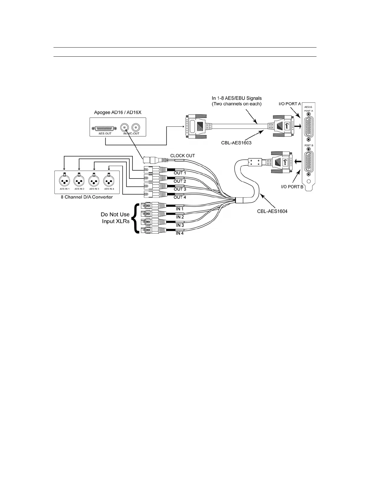
The figure below illustrates a “mixed mode” configuration, where the AES16 is connected to an Apogee
AD16X 16-channel Analog-to-Digital converter and to some other 8-channel Digital-to-Analog converter.
This represents a unique situation, in that the AD16X will utilize all 16 available input channels while
connected to a single I/O port of the AES16, while only 8 output channels will be available to the D/A
converter.
The AD16X is connected to the AES16 via our CBL-AES1603 cable, which is specifically designed to
accommodate the Apogee 16-channel converters through their D-Sub port. I/O Port B in this example is
connected to an 8-channel D/A converter using our CBL-AES1604 cable with standard XLR connections.
It is critical that the AES/EBU inputs on the CBL-AES1604 cable NOT be connected to any external
device since these inputs are connected electrically to inputs on I/O Port A. Doing so will degrade the
quality of the digital signal received on I/O Port A. Consequently, this configuration is limited to 16
input channels and 8 output channels, rather than the 16 in and 16 out which are possible with other
cable set combinations.
PLEASE NOTE: Since the CBL-AES1605 supports input and output signals through a single connector, it
is not advisable to use the CBL-AES1605 with the CBL-AES1603 at the same time.
In this example, the AES16 will function as the system clock master, with the Apogee AD16X and 8-
channel D/A converter acting as clock slaves. As shown, the word clock output available on the BNC
connection of the CBL-AES1604 cable is connected to the word clock input on the Apogee AD16X. The
D/A converter can receive its clock via the AES/EBU signal from the AES16, or from the word clock out
of the AD16X. If the word clock is used, a connection from the AD16X word clock out to the D/A word
clock in is required.
I/O Configuration Jumper Settings
When using the CBL-AES1603 connected to an Apogee 16-channel converter, the associated I/O port on
the AES16 must be set to 8 CHNL mode. For this example, set the jumper for I/O Port A to 8 CHNL mode.
Confirm that the I/O Port B jumper is in the factory default 4/4 CHNL mode. See Section 12.1 I/O
Configuration Jumpers for more information.
AES16 User Manual 30