Operational Overview
5 Operational Overview
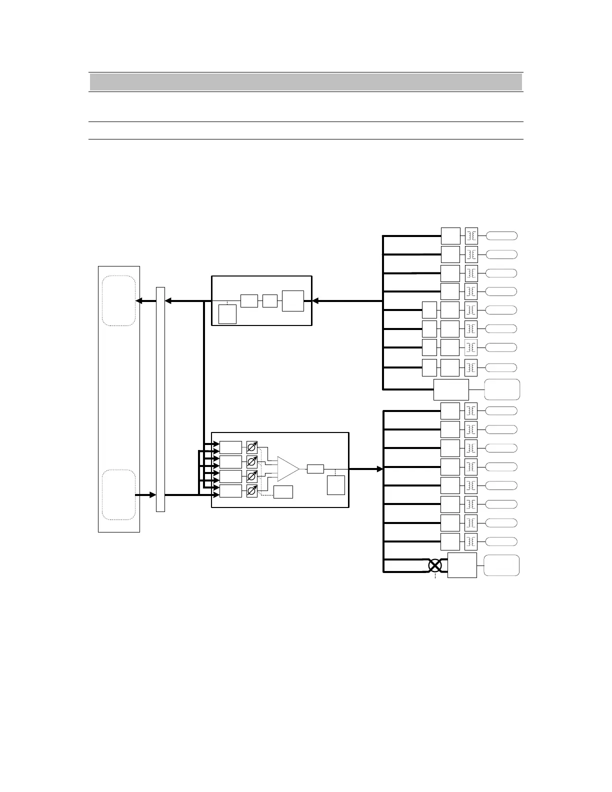
5.1 Signal Flow
As shown in the signal flow diagram below, the
AES16 with its on-board digital mixer provides
extensive signal routing capabilities that can
adapt to any studio requirement. The mixer is
implemented using a proprietary digital signal
processor (DSP) that is optimized to maintain
low latency and high signal quality.
The architecture of the digital mixer consists of
16 record channels and 16 play channels that are
accessible to host applications as eight stereo
record devices and eight stereo play devices.
Submixers on each output provide low-latency
mixing for record monitoring and output mixing.
Output Bus 15,16
Output Bus 13,14
Output Bus 11,12
Output Bus 9,10
Output Bus 7,8
Output Bus 5,6
Output Bus 3,4
Output Bus 1,2
Output Bus
(16 signals)
Play Bus
(16 Channels)
Monitor
Se l ect
Monitor
Se l ect
Monitor
Se l ect
Monitor
Se l ect
Master
Fader
SUM Dither
Peak
Level
Meter
AES-3
XMIT
OUT 1
LStream
Header Port
Output
Output Bus 1..8
1-8 / 9-16
Sel ect
Output Bus 9..16
Input Bus 9,10
Input Bus 5,6
Input Bus 3,4
Input Bus 1,2
Input Bus (1..32)
(32 signals)
LStream
Header Port
Input
Input Bus 17..32
LStream
Recei ver
Input
Patch
Sel ect
MuteDither
Record Bus
(16 Channels)
SR C
Peak
Level
Meter
LStream
Transmitter
PCI
BUS
Stereo
Record
Devices
1 - 8
Stereo
Play
Devices
1 - 8
AES16 Driver
Installed in Host
Computer
Digital Mixer Input Block
( 1 of 16 )
Digital Mixer Ouput Submixer
( 1 of 16 )
AES-3
RECV
IN 5
AES-3
RECV
IN 1
AES-3
RECV
IN 2
AES-3
RECV
IN 3
Input Bus 7,8
AES-3
RECV
IN 4
Input Bus 11,12
SR C
AES-3
RECV
IN 6
Input Bus 13,14
SR C
AES-3
RECV
IN 7
Input Bus 15,16
SR C
AES-3
RECV
IN 8
AES-3
XMIT
OUT 2
AES-3
XMIT
OUT 3
AES-3
XMIT
OUT 4
AES-3
XMIT
OUT 5
AES-3
XMIT
OUT 6
AES-3
XMIT
OUT 7
AES-3
XMIT
OUT 8
Figure 4: Signal Flow Diagram
AES16 User Manual 39