Hardware Connections
3.3.2 Internal Clocking and Multi-card Systems
Clock connections to internal equipment are provided via the header CLOCK IN and CLOCK OUT
connectors on the AES16 board. Refer to Figure 1 for the location of these connectors. The connectors
support 75-ohm, TTL level signals. If you are connecting to another Lynx digital audio card, the Lynx
Internal Clock Cable (CBL-ICC) or Universal Clock Cable (CBL-UCC) should be used.
Connect the CLOCK IN connector to the clock output of an internal device and select “Header” as the
clock source in the Lynx mixer. Adjust the clock Reference to match the incoming clock type.
The signal on the CLOCK OUT header is a word clock that tracks the sample rate of the AES16. Connect
this output to the word clock input of an internal device or another AES16.
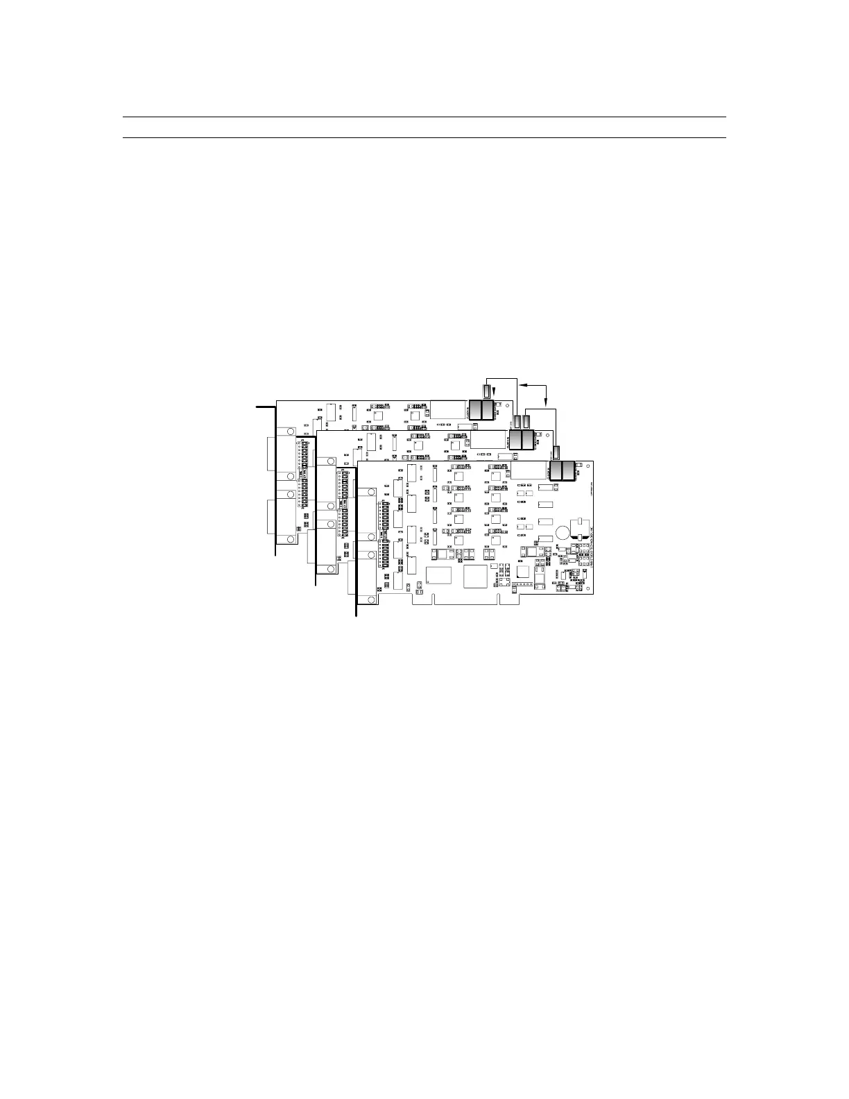
As shown below in Figure 3, multiple AES16s can be synchronized using the optional Internal Clock
Cable. A daisy chain of CLOCK OUT to CLOCK IN is created so that all cards are tightly synchronized.
Refer to Section 9 Configuring Multiple AES16’s for more information.
I/O PORT A
I/O PORT B
LSTREAM
AES16 Master
Internal Clock Cable
I/O PORT A
I/O PORT B
LSTREAM
AES16 Slave 1
AES 16
I/O PORT A
I/O PORT B
LSTREAM
AES16 Slave 2
Figure 3: Synchronizing Multiple AES16's Using Internal Clock Connections
Note: If an appropriate internal clock cable is not available, multiple cards can be synchronized externally
by using the BNC clock connections on the CBL-AES1604 cable. Use a standard 75-ohm BNC coaxial
patch cable to connect the input clock signals to the output clock signals.
AES16 User Manual 27