© 2017 MacroAir Technologies Toll Free: 866 668 3247 Fax: 909 890 2313 www.macroairfans.com 9
Rev. Date 032217
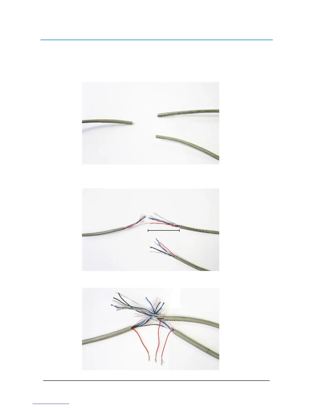
Connection Method
1. Take the incoming CAT5 from the network, the CAT5 from the fan, and the CAT5 going to the
rest of the network. Give some slack (no more than 24”) on each CAT5 to strip the wires and
splice them together. Run the slack up towards the ceiling and back down in a horseshoe shape.
DO NOT roll the excess slack into a circle or coil because this creates a place for the network to
pickup noise on the lines.
2. Strip jacketing off the three CAT5 cables and separate each color wire leaving approximately 2
inches of each wire exposed including the drain/shield wire.
3. Strip approximately 1/2 inch off each color wire leaving the bare copper exposed.
2 inches