© 2017 MacroAir Technologies Toll Free: 866 668 3247 Fax: 909 890 2313 www.macroairfans.com 12
Rev. Date 032217
Temp/Humidity Sensor Installation
(Optional)
Mounting
1. Mount the floor temperature sensor in the room where the fan/fans are placed within 3ft of
the ground. Use caution when placing the sensor making sure not to place it where there is any
contact with direct sunlight. Refer to the wiring diagrams on page 8 for placement in the CAT5
run.
2. Once the module has been placed it can be wired into the network. Use the brown pair to power
the temperature sensor and the blue pair for communication. If there is enough slack in the cable
you can run the wiring directly in and out at the same point on the sensor module.
3. If there is not enough wire to pull in and out of the sensor splice a length of cable keeping
length to a minimum. Use the bean crimps supplied by Macro Air to wire the lead into the
network. Please refer to network wiring diagram on the following page.
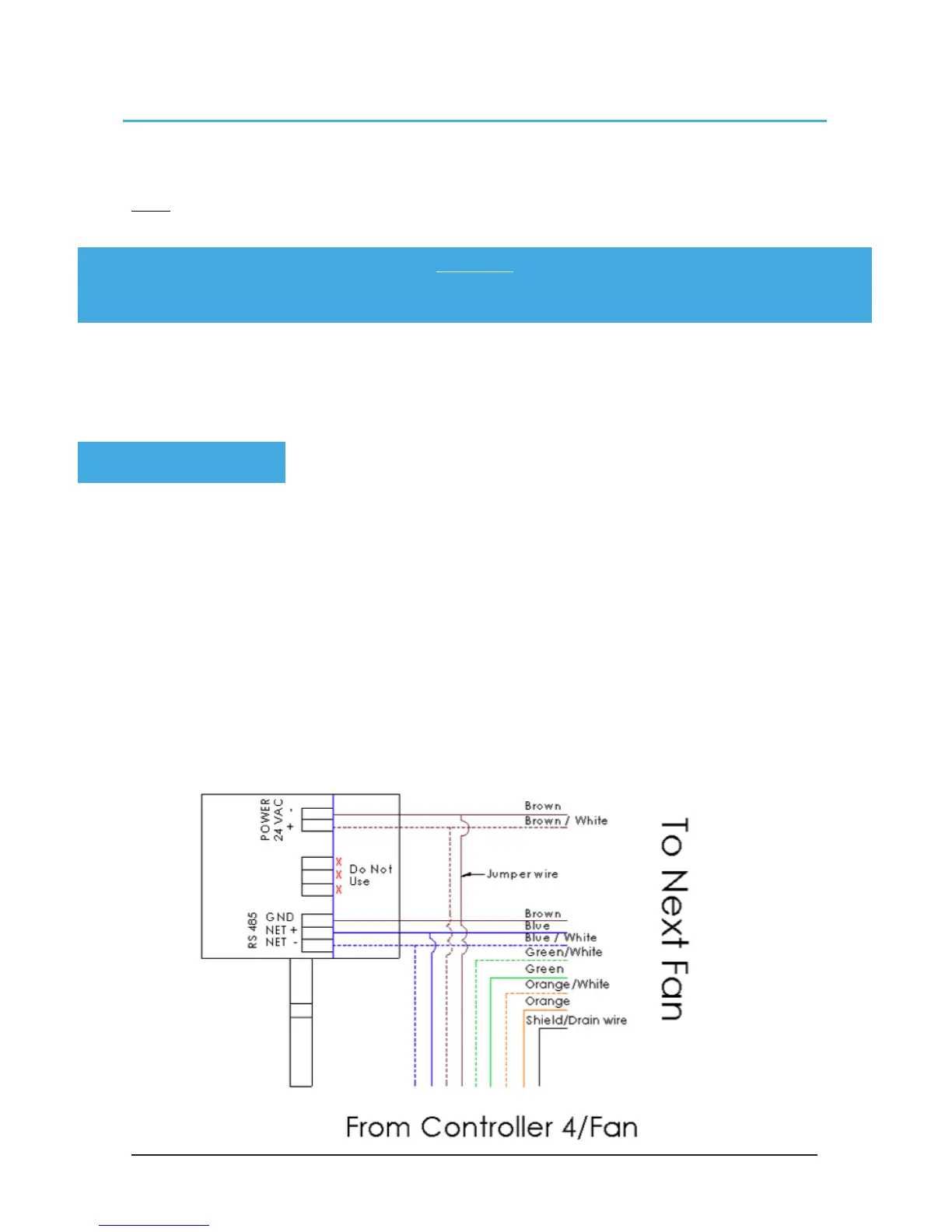
Please refer to the wiring diagram below:
Note: This section of the manual is applicable only if you ordered optional temperature
sensor feature.
Brown - 24VAC- jumpered to GND
Brown/white - 24VAC+
Blue - Net+
Blue/white - Net-
WARNING:
Do not mount the temperature probe on metal as it will then be reading the temperature
of the metal rather than the air temperature.
PINOUT: